
NS-5A Comprehensive Monitoring Controller Technical Description:
Note:The combined controller's terminal 19 and 20 fault output can be input to a PLC or connected to an alarm.
2. All pump signal lines are designated. For example, line 31# is called P31, line 32# is called P32, and so on.
3. If the pump lacks a bearing signal lead 61#, short circuit controller terminals 7 and 10; 4. If the pump lacks winding signal leads 11#2# or 21#22#, short circuit the integrated controller terminals 11 and 12.
5. If there are no other signal leads coming from the pump, the corresponding terminal on the integrated controller is left empty.
6. If the meter alarms after powering on and connecting the pump signal lines, a reset can be performed using the reset button.
7. Terminal 15 and 16 of the controller are for overload signal input, typically connected to the normally open contact of a thermal relay.
Controller terminal 17 and 18 are the stop-pump signal input, typically connected to the normally closed terminal of an AC contactor.
2.4: Technical Specifications
Ambient Temperature: -20℃ to 70℃
Relative Humidity: ≤90%RH, non-condensating, non-corrosive gas-free environment
Operating Voltage: 220V/50Hz
Controller Power Consumption: ≤ AC 4W
Fault Output Capacity: 5A/AC220V
Dehumidification Output Capacity: 5A/AC220V
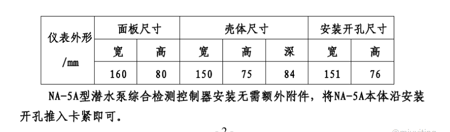
Controller Dimensions: 160mm x 80mm x 90mm
Panel Aperture Size: 151mm x 76mm
Weight: 0.4 kg
2.5: Installation Specifications and Instructions
Controller Dimensions: 160mm x 80mm x 90mm
Control Panel Cutout Dimensions: 151mm x 76mm
Controller Installation Method: Panel Insertion Installation
During wiring, to prevent signal interference, please use shielded cables for control lines as much as possible.
If there is no corresponding signal input for the controller, it will not affect the normal operation of the entire controller; however, the controller will be unable to perform the corresponding protective function.
Prior to testing, please carefully check the wiring of the control cabinet and the controller. Once confirmed correct, close the power to the control cabinet to put the system into operation mode.
In the event of a pump fault alert during operation, after confirming and resolving the issue, the reset button must be pressed once, followed by a 2-second delay, or the power must be cycled to allow the controller to resume normal operation.
3.1: Oil Pump Chamber Leak Protection
During the operation of the submersible pump, leakage failures in the oil chamber may occur due to reasons such as mechanical seal wear, which can threaten the normal operation of the pump. The protector is connected to the pump via signal lines. P31# P32# Signal lines monitor it; when the resistance is less thanAlert ThresholdAt that moment, the red warning light indicating oil leakage in the oil chamber flickered, when the sensor value exceededAlert ValueAt this time, the warning indicator light stops flashing and remains a steady green light. When the resistance is less thanAlarm ValueAt the moment, this protective device is delayed.2 seconds later, faults 3 and 4 output, the normally closed points are disconnected, cutting the control circuit, forcing the pump to shut down, while the red light indicating oil chamber leakage remains constantly illuminated; when the resistance of the sensor recovers to greater than...Alarm ValueAt this time, the relay and red indicator light are still in the faulty state. To clear the fault, you need to manually hold down the reset button on the panel.2S or more is required to return to normal status. Points 19 and 20 are commonly used for fault output, such as connected to PLCs. (Note: 1: Fault output does not operate during the early warning; 2: In normal condition, the green indicator light is constantly on.)
3.2: Pump Motor Ingress Protection Against Water Immersion
During the operation of the submersible pump, due to reasons such as seal wear and tear...When the pump motor cavity encounters an immersion fault, it poses a threat to the motor's safety. The protector monitors the fault through the P51#P32 signal lines on the pump, when the resistance value is less thanAlert ThresholdAt the moment, the red alarm indicator light for internal cavity leakage is flashing, when the resistance is greater than...Alert ThresholdWhen the indicator light no longer blinks and turns to a steady green light, it indicates that the resistance is less than...Alarm ValueAt that time, the device was delayed.2 seconds later, the red light for internal cavity leakage is continuously lit, while fault outputs 3 and 4 are disconnected at their normally closed points, and normally open contacts 19 and 20 are closed. When the resistance of the sensor recovers to be greater than...Alarm ValueAt the moment, the fault relay and the red indicator light remain in their faulty state; to clear the fault, you need to manually hold down the reset button on the panel.2S or more is required to return to normal status. (Note: 1: Fault output does not act during the alarm; 2: In normal status, the green indicator light is constantly on.)
3.3: Pump Wiring Box Internal Immersion Protection
During operation, a leak in the motor junction box cavity of the submersible pump poses a risk to motor safety; the protector on the pump detects and mitigates this issue. P41#P32# Signal lines monitor it, when the resistance is less thanAlert ThresholdAt present, the red alarm indicator light on the line box flickers due to leakage; when the resistance is greater thanWarning LevelAt this point, the warning indicator light stops blinking and remains constantly green; when the resistance is less thanAlarm ValueAt the moment, the device is delayed.2 seconds later, the red light indicating leakage in the wire box remains lit, while fault outputs 3 and 4 activate, the normally closed point opens, and the normally open points 19 and 20 close, when the resistance value recovers to greater thanAlarm ValueAt the moment, the fault relay and the red indicator light remain active. To eliminate the fault, you need to manually hold down the reset button on the panel.2S or more is required to return to normal status. (Note: 1: During the alarm, the fault output does not activate; 2: In the normal state, the green indicator light is constantly on.)
3.4: Pump Overload Protection
When the submersible pump operates and the motor malfunctions due to overcurrent (overload, phase loss, or phase failure), the thermal relay acts, and this device delays.2 seconds, fault 3 and 4 outputs, break points disconnected, 19 and 20 normally open nodes closed, the panel's pump overload indicator light illuminates at the protective value, remaining constantly lit until the fault is resolved. To restore to normal status, manually hold the reset button on the panel for over 2 seconds. (In normal conditions, the indicator light does not illuminate.)
3.5: Pump motor insulation, moisture-proof control
Due to the operation of the submersible pump underwaterHigh humidity inside the motor cavity can lead to condensation on the winding surface when the motor is shut down, due to the decrease in winding temperature, which in turn reduces the insulation of the motor windings. To stabilize the insulation of the motor windings, the protector monitors them through the P71# and P32# signal lines on the pump, when it detects...Drop Point SignalAt the same timeUpon detecting a shutdown signal delay of 18 seconds at terminals 17 and 18, the device connects the 13 and 14 dehumidification heating normally open nodes. The dehumidification indicator light on the protector panel remains constantly lit, and the heating dehumidification control relay operates, causing the AC contactor KM4 to close. This applies the transformer's low voltage and high current to the pump motor, raising the winding temperature above the dew point, preventing condensation from forming on the winding surface. The motor insulation remains stable until the temperature reaches 70%, at which point the heating automatically stops. If the motor starts, the control system immediately ceases operation.
NoteThis feature can only be activated during pump shutdown; otherwise, it may cause serious short-circuit accidents.
3.6: Pump Motor Winding Overheat Protection
During the operation of the submersible pump, due to overload, phase failure, or missing phase, the winding temperature abruptly increases. When the temperature exceeds...At 135°C, the protector is monitored through the P11#P12# or P21#P22# signal lines on the pump. When the resistance is greater thanWarning ThresholdWhen the winding overheats, the red warning indicator light blinks; when the resistance is less thanAlert ThresholdAt this time, the warning indicator light stops blinking and turns to a steady green light; when the resistance value exceedsAlarm ValueAt that time, the red light indicating winding overheating is constantly on, while the protective device's action is delayed.In 2 seconds, fault 3 and 4's normally closed points are disconnected, while points 19 and 20 close normally. When the resistance value recovers to less than...Normal ValueAt the moment, the fault relay and the red indicator light are still in the faulty state. To eliminate the fault, you need to manually hold down the reset button on the panel.2S or more is required to restore to normal status. (Note: 1: During the alarm, the fault output does not act; 2: In normal state, the green indicator light is constantly lit.)
3.7: Pump Bearing Over-Temperature Protection:
When the submersible pump experiences failure in the pump bearing due to overloading or other reasons, the temperature spikes, when the temperature exceedsAt 135°C, the protector monitors itself through the P61#P32 signal line on the pump, when the resistance of the PTC is greater thanWarning LevelAt that time, the red early warning indicator light for bearing over-temperature flickered, when the resistance was less thanAlert ThresholdAt this time, the warning indicator light stops blinking and turns to a steady green light. When the resistance value exceedsAlarm ValueAt the time, the device experienced a delay.In 2 seconds, the red light indicating bearing over-temperature remains lit, while Fault 3 and 4 outputs are activated, the normally closed node is disconnected, and the normally open points 19 and 20 are closed. When the resistance of the PTC returns to greater than...Normal ValuesAt the moment, the fault relay and the red indicator light remain unchanged. To clear the fault, you need to manually hold down the reset button on the panel.2S or more is required to return to normal status. (Note: 1. Fault output does not act during the first alarm; 2. The green indicator light is constantly on in normal operation.)