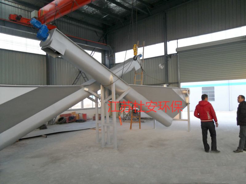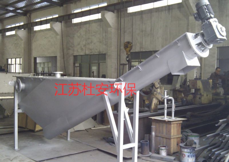

Duwan Environmental ProtectionLSSF-320Sand and Water Separator Installation and Commissioning Instructions:
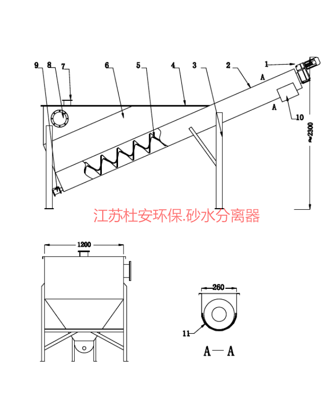
Sewage separator mainly consists of a shaftless helical screw, strips,UThe assembly includes mold slots, water tanks, guide vanes, and water outlet weir drive units.
Installation and Commissioning:
1In the absence of specification in the order contract, the machine is factory-equipped with a ground support bracket, already adjusted according to the user's equipment installation angle or discharge height, and is secured during installation with expansion bolts.
2Equipment installation angle tolerance is ±1Degree
3During hoisting, collisions and slips are strictly prohibited, and effective measures must be taken to protect the stainless steel surface of the equipment, ensuring no scratches, wear, or dents are present.4Ensure the correct level of reducer oil before starting up.*Next Use300Change lubricating oil every hour, operate continuously for over16Hour's equipment, every2500Change hourly, operate daily8Hourly equipment extendable to4000Hour.
5During the commissioning test, the machine should be manually started to ensure there is no component friction before entering normal operation.
Separator for Sand and Water: Usage and Maintenance
1Operators must be trained and qualified before they can start operating.
2Equipment is inspected, maintained, repaired, and lubricated in accordance with the normal routine, maintenance, repair, and lubrication management systems.
3Daily inspections of machine operation are conducted, ensuring no abnormal noises, checking for leaks in seals, and appropriately adding bearing lubricant. Monthly checks of the oil level in the drive unit gear box are performed, and the level is topped up to the required height.
4Every two years: the equipment undergoes a complete disassembly and overhaul, including the dismantling and cleaning of the reducer, replacement of worn parts, and the exchange of seals and worn bushes. Additionally, the helix is inspected and corrected.
5The system must be shut down due to a malfunction, and the cause must be identified before it can be restarted.
6When machinery is down for three days or more, flush or expel internal materials to prevent drying and caking.
7During low winter temperatures, anti-freezing measures should be taken. Dislodge any blockages or ice formations before powering on. If supplied as a complete set with other equipment, the control buttons are centralized in a single control box.
Duane LSSFType Spiral Sand and Water Separator
Product Name:LSSFTapered Spiral Sand and Water Separator
Product Price:25800 Translation not provided due to the lack of Chinese content.
Product Market Price:29800 Please provide the Chinese content to be translated.
Product Specifications:LSSF-320
Product Nickname: Solid-Liquid Separator
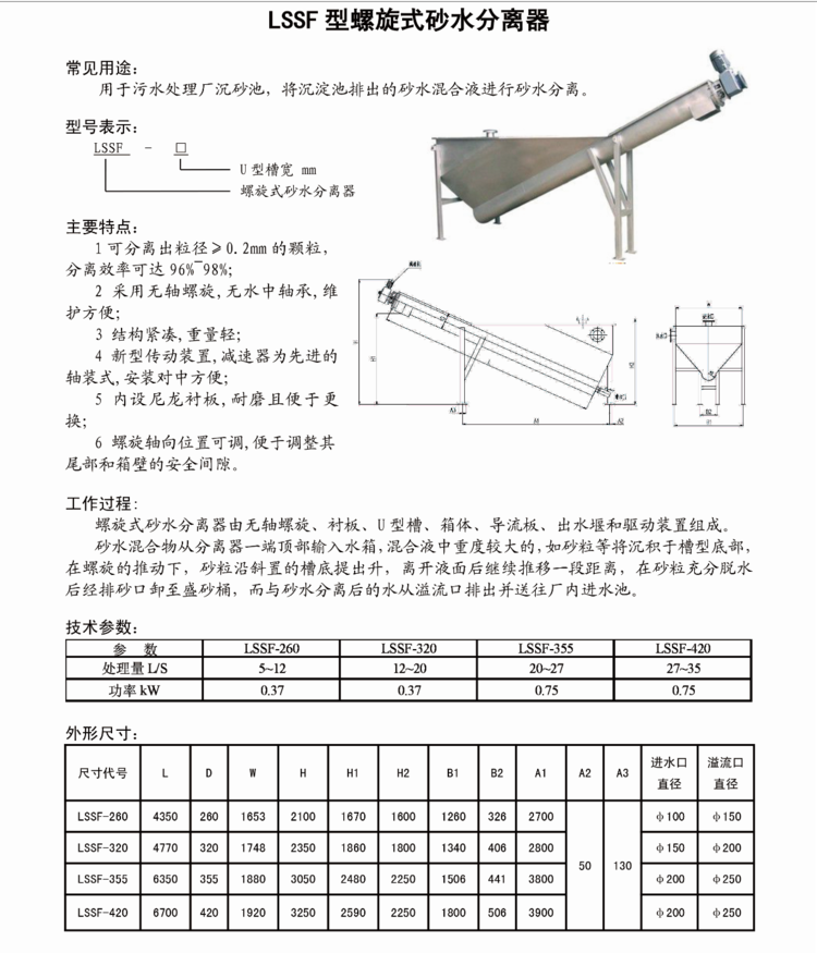
Application Scope: Used in sedimentation basins of wastewater treatment plants to separate sand and water mixtures discharged from sedimentation tanks.
Purpose:
The company's new product is designed for sedimentation basins in wastewater treatment plants, effectively separating sand and water from the effluent.
.png)
The Jiangsu Du'an Environmental Protection Sand and Water Separator Technical Specifications and Installation Size Table mainly includes nominal helix diameter, helix diameter, processing capacity, installation angle, helix rotation speed, motor power, recovery rate, water content rate after sand separation, and installation dimensions.
Model Specifications | -260 | -300 | -350 | -400 | |
Helical Nominal DiameterD(mm) | 260 | 300 | 350 | 400 | |
No Chinese content provided.(m7h) | 235 | 285 | 320 | 385 | |
Volume processedQ(m3/h) | 5-12 | 12 〜20 | 20 〜27 | 27 〜35 | |
Installation Anglea(° ) | 25 | ||||
Screw Rotation Speedn(r/min) | ≈4.8 | ||||
Motor PowerN(KW) | 0.37 | 0.55 | 0.75 | ||
Recycling Rate(Particle size ≥0.2mm) | ≥96 | ||||
Post-sand separation water content rate(%) | <65 | ||||
φA | 220 | 270 | 320 | 390 | |
B | 260 | 310 | 345 | 410 | |
B1 | 710 | ||||
b2 | 1200 | 1360 | 1500 | 1800 | |
b3 | B2+80 | ||||
Installation Dimensions | DN, | 100 | 150 | 200 | 250 |
(mm) | dn2 | 150 | 200 | 250 | 300 |
L | 2800 | 3000 | 3200 | ||
L1 | 3840 | 4380 | 5760 | 6150 | |
l2 | 2800 | 2800 | 3800 | 3800 | |
H | 1550 | 1750 | 2400 | 2550 | |
H, | 1600 | 1700 | 2150 | 2150 | |