
Submersible污水泵Installation Instructions for the Automatic Coupling Device:
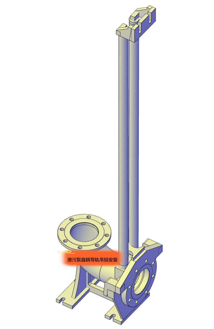
This description applies to the wet installation method of submersible pumps. (Please refer to the following part numbers below.)"Automated Coupling Device Axial Diagram)”
Pre-treatment before installation process. Note: Process A is required for DN200~DN500. No process needed for DN50~DN150.
1. The location of the base (11) foot bolt holes.
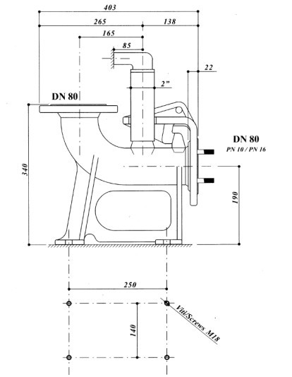
Prior to the concrete pouring in the sewage pond, ensure that the foot bolt holes for the base (11) are pre-drilled. The center of the pre-drilled holes aligns with the position of the base fixing bolts as indicated in the base fixing bolt layout diagram (refer to Table 1), with the size of the pre-drilled holes being 100*100 square holes.
2. Further, the Z-axis and the center of the outlet pipe must align with the centerline of the foot bolt预留孔 and the centerline of the pool mouth support block, all within the same axis plane. The dimensions must also comply with the requirements of the installation system diagram before pouring can proceed.
B. Installation Process
Identify the position of the support block (2).
Draw a vertical line on the wall of the pool opening on the side of the drainage pipe, ensuring that the line is within the plane of the center of the drainage pipe. This vertical line serves as the support block.2) Install symmetrical baseline.
2. Install support block (2)
Please provide the Chinese content to be translated.The central line of (2) aligns with the installation baseline at the pool mouth. Drill two holes at the center of the pool wall at the spacing of the槽 of the support block (2), according to the size of the expansion bolt screws. Insert the expansion bolt (1) to secure the support block (2), but do not tighten it all the way.
3 - Mounting Base (DN50~DN150)
3.1 - Ensure the correct position of the base, place the base at the bottom of the pool. Attach a plumb line to the self-supporting block (2) to align it with the centerline of the support block (2). Locate the centerline of the base (11) using the plumb line, and ensure that the centers of the two cones on the support block (2) and the two cones on the base (11) are on the same vertical plane. Mark the position of the base (11)'s foot bolt holes.
3.2 - Bottom bracket (11) base screw holes: Remove the bottom bracket (11), drill holes directly according to the marked positions and the size of the expansion anchor bolts (12), clean out the debris from the holes, place the bottom bracket (11) back, insert the bolts (12) and tighten them.
3 - Base Mount (DN200~DN500)
3.1 - b Correct Installation Position for Base (11): Place the base (11) at the bottom of the pool. Hang a plumb line from the self-supporting block (2) so that it aligns with the centerline of the block (2); locate the centerline of the base (11) using the plumb line, ensuring that the centers of the two cones on the self-supporting block (2) and the two cones on the base (11) are in the same vertical line. Adjust the position of the ground bolts in the reserved holes.
3.2b - Pouring reserved holes, fill the reserved holes with concrete, ensuring the position of the anchor bolts within the holes and the length of the bolts extending above ground. Recheck the installation dimensions of the anchor bolts after the pouring is complete.
After casting, the maintenance period is15 days (Note: High-quality concrete and sufficient footing thickness are indispensable conditions for the vibration-free operation of the pump.)
4. Installation guideTrack
If the depth of the pool is less than6 meters, then saw the two conduits (10) to the appropriate length and securely install them between the support block (2) and base (11). Ensure each end fits into the conical shape of the support block (2) and base (11) respectively, and that the conduits are kept perfectly vertical.
If the depth of the pool is greater than6 meters, connect the conduit (10) to the short conduit (3) using the union (5), secure it with an internal hexagon bolt (4), and then place the conduit between the support block (2) and the base (11), ensuring it remains vertical.
5. The system consisting of the fixed support block (2), base (11), and conduit (10).
Re-inspect the bearing blocks2) Ensure that the导管 (10) and base (11) are vertically aligned, and that the centerline of the support block (2) coincides with the centerline of the base (11) within the same plane. Then, securely tighten all screws in the fastening system, ensuring that the entire system has no movement in either the vertical or horizontal direction.
6. Drainage pipeline installation
According to the installation diagram, connect the drainage pipes sequentially with bolts and sealing washers, and attach flexible rubber joints, elbow pipes, wall outlet pipes, swing check valves, and wedge gate valves, then fill the gap between the wall outlet pipe and the wall with concrete.
7. Install bracket
Please provide the Chinese content to be translated into American English.6) Within the embedded bracket (7), pay attention to the directional installation of the face washer (6). The rubber flange edge that is the same thickness interfaces with the electric pump flange surface, while the rubber flange with a thicker and thinner side interfaces with the base. Ensure the thicker side is at the top of the installation hole. Secure the bracket to the pump outlet flange using bolt (9) and washer (8), and tighten the bolts diagonally alternately to ensure a seal.
8. Hoisting Water Pumps
Attach the chain to the lifting loop of the electric pump, hoist the pump, sliding it along the conduit into the sewage pool, and then secure it in place on the base.11) The ribs on both sides of the plate allow the pump to automatically achieve the correct working position due to the weight of the pump itself, ensuring the sealing performance between the pump outlet and the base.
9. Adjust the float switch position
Users can adjust the float switch position according to design requirements or personal needs to control the start and stop of the electric pump based on the water level changes within the pool, ensuring that the liquid surface submerges the vortex shell.
10. Enclosed suggestions
After installation, the concrete slope at the bottom surface can be irrigated. The choice of the slope around the waste pool should be suitable for the pool's dimensions. Generally, the horizontal to vertical dimension ratio is determined.2:1
11. Hoisting of the pump
To facilitate the hoisting of the water pump for users, the pump features a loop. Before lifting the electric pump, hang the loop from the crane hook, thread a nylon rope and chain through the circular hole, pull the rope end straight, and let the loop slide down the nylon rope and chain links. When it reaches the proper position, loosen the nylon rope, and a chain link will lock with the loop. At this point, you can lift the pump. The loop can also be used to safely and conveniently place the pump in the designated location.
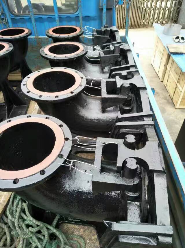
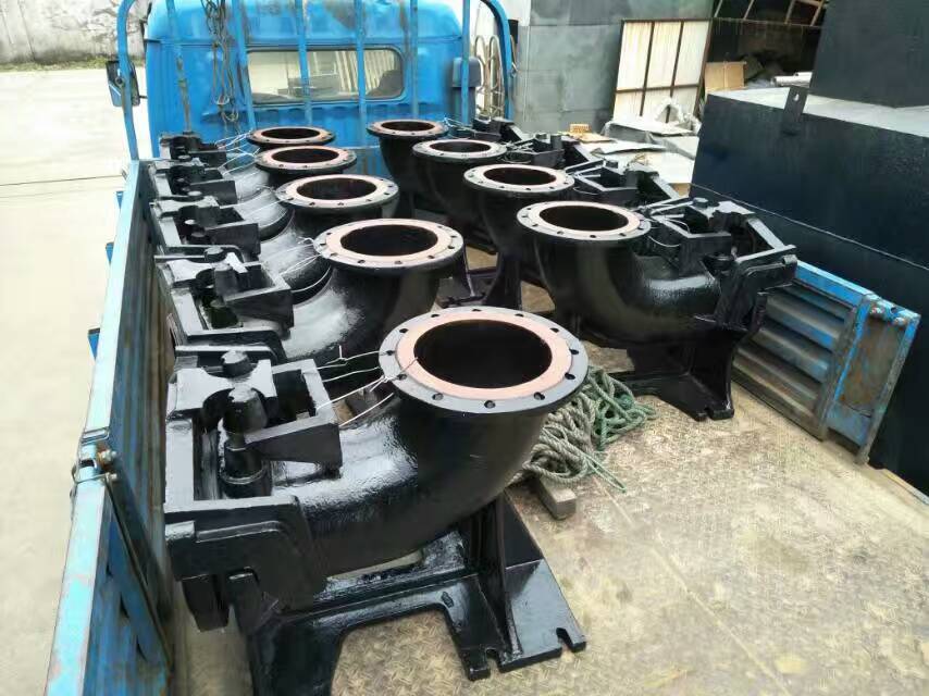
Jiangsu Environmental Protection Co., Ltd. offers the following cast iron automatic coupling devices:
GAK50 Automatic Coupling Device (Cast Iron) for Submersible Sewage Pumps
GAK65 Automatic Coupling Device (Cast Iron) for Submersible Sewage Pumps
GAK80 Submersible Sewage Pump's Automatic Coupling Device (Cast Iron)
GAK100 Submersible Sewage Pump with Automatic Coupling Device (Cast Iron)
GAK150 Submersible Sewage Pump with Automatic Coupling Device (Cast Iron)
GAK200 Model Submersible Sewage Pump with Automatic Coupling Device (Cast Iron)
GAK250 Type Submersible Sewage Pump with Automatic Coupling Device (Cast Iron)
GAK300 Submersible Sewage Pump's Automatic Coupling Device (Cast Iron)
GAK350 Submersible Sewage Pump's Automatic Coupling Device (Cast Iron)
GAK400 Submersible Sewage Pump with Automatic Coupling Device (Cast Iron)
GAK450 Submersible Sewage Pump Automatic Coupling Device (Cast Iron)
GAK500 Submersible Sewage Pump with Automatic Coupling Device (Cast Iron)
GAK600 Submersible Sewage Pump with Automatic Coupling Device (Cast Iron)