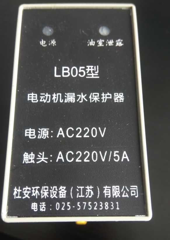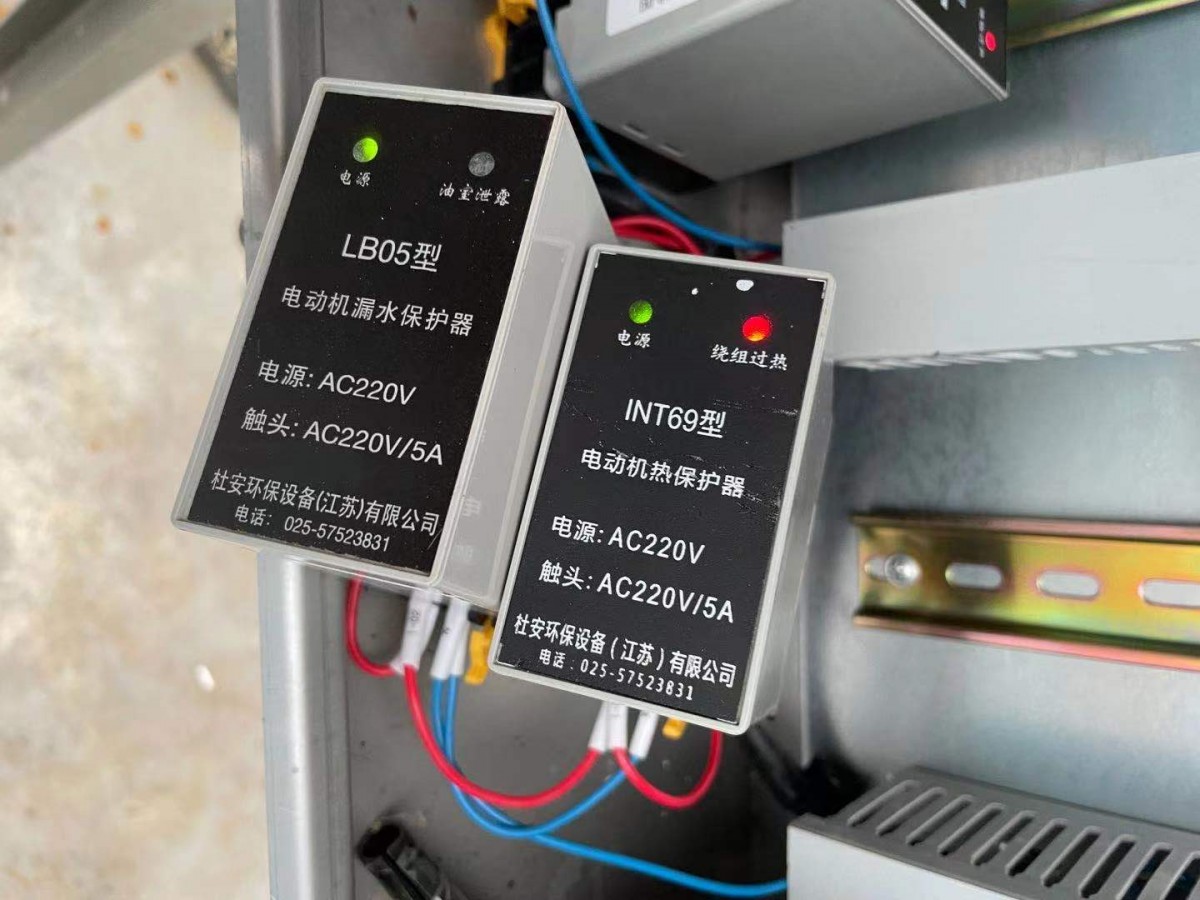

LB-05 Leak Protection Device
1.Overview
LB-05The Water Leak Protection Relay, also known as a Miniature Comprehensive Protection Device, is specifically designed to detect the water-sensitive resistance and motor temperature signals within submersible pumps..Electrode Sensors Utilized in Sensors.When leakage occurs within the pump body or abnormal temperatures are detected.,The control relay will emit the corresponding control signals.,To facilitate staff in addressing the water leakage from the pump..The controller has adopted a series of anti-interference measures in circuit design.,Operates reliably in environments with severe electromagnetic interference.
2.Feature Description
The protector is used to detect the resistance and winding temperature signals of water sensitivity inside the submersible pump.PTCOr temperature switch).When the resistance of the water sensitivity inside the submersible pump falls below the given value,Relay activation;The protector resumed operation after power was restored following a fault clearance during a power outage and the system was reenergized..When a temperature signal is detected as an open circuit or with a high resistance,Protector's relative application indicator light alarm,Simultaneous operation of the fault relay.
LB-05Model (Default Product):No content provided.,Fault signal output is normally open,In the event of power outages or input signal malfunctions,Constant Open Signal to Constant Closed Signal.
LB-09Model:Normal conditions,Fault signal output is a normally closed signal.,When power is disconnected or input signal fails,Change from normally closed signal to normally open signal.
The panel indicator lights can separately display the type of alarm.,The reset button can manually reset the fault when the water sensitivity resistor is set according to standard..Customers with special requirements may contact us in advance..

3.Product Panel Description
Overheating/P:Winding Overheat Indicator,The lights are not on as usual.,Red light illuminates during pump overheating fault.
Leak/S:Oil chamber leakage indication,Normal, lights not on,Red light illuminates during pump oil chamber leakage failure.
Reset/R:Reset Button,In the event of a fault, the protector will lock.,Reset manually by pressing the reset button.
Power Supply/L:Power Indicator,Power on, green light,Power to the protector, and the green light is on..
4.Technical Specifications
Input Signal:
Leakage Input:Resistive signal or normally open signal,Water-sensitive resistor ≤30KΩ.
Overheated input:PTCResistive Signal or Normally Closed Signal.
Sensor Power Supply:DC12V
Signal Control:Response Speed20mS,Return Difference Control ±5%
Ambient Temperature:-20℃~70℃
Relative Humidity:≤95%RH,No condensation,Non-Corrosive Gas Environment
Operating Voltage:220V/50HZ
Controller Power Consumption:≤ AC 2w
Fault Output Capacity:5A/AC220V 5A/30VDC
Controller dimensions:48mm*80mm*120mm
Installation Method:DIN35Guide Rails
Weight:0.3kg
5.Wiring Terminal Description:
1.Terminal1、2(L N):
Power Supply for Protectors220V 50HZ,Power Supply Connected, Panel "Power"/LGreen light.
2.Terminal3、4(S-IN):
Pump leakage input signal,Typical pump for water intakeP31 P32Signal Line.Detectable signal outputs for pump oil chambers, junction boxes, motor cavities, humidity electrodes, or switch quantities,Signal is normal.,Leak/SThe indicator light is not illuminated.,When electrodes or switch quantity signals are abnormal,Leak/SThe indicator light is red..
3.Terminal5、6(P-IN):
Pump Overheat Input Signal,General PumpP11 P12Signal Cable.Detectable for pump winding, bearing, and stator placementPTCResistor or normally closed switch quantity output signal.Signal is normal,Overheated/PThe indicator light is not illuminated.,When the signal is abnormal,"Overheated/P"The indicator light is red..
No additional content provided.:When there is no overheating signal,Wire short-circuit5 6Terminal.4.Terminal7、8(Out):Total Fault Output,Capacity5A/220VAC 5A/30VDC。
ZJK-9(-NOOutput is disconnected when there is no fault.,Fault becomes closed;ZJK-9-NCOutput is closed when there is no fault.,Output becomes disconnected during failure.
6.Dimensions and Installation Diagram(Wide*High*Long)With Installation Base48*80*120 (mm)
LB-05Motor Leak Protection Device Dimensions:48mm*80mm*86mm
Installation Base Dimensions:48mm*80mm*34mm
LB-05Motor Leak Protector Installation Method:Adopting international standardsDIN35Track Installation,Inlaid within the control cabinet,Secure with random fasteners only..
Please check the wiring of the control cabinet and controller thoroughly before debugging.,Confirmed accurate,Shut down the control cabinet power,Keep the system operational.
7.After-Sales Service
Products can be returned within one month of purchase.,30-day money-back guarantee,One Year Free Repair,Lifetime Maintenance Service.During use, for technical assistance,The company has established a professional marketing and customer service department.,Complimentary pre-sales, in-sales, and after-sales technical consultation, as well as installation and debugging guidance for users.,Addressing Issues Encountered by Users During Usage.
LB-05 AC220V 5A Leak Protector