


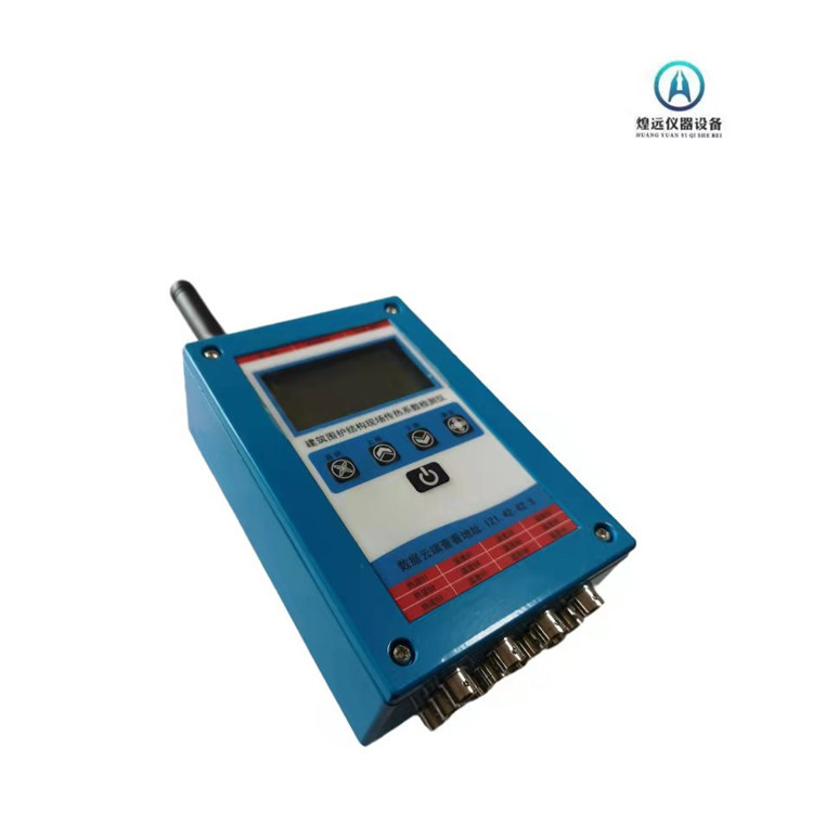
Thermal Conductivity Wall Tester
Model:HY12 (Wireless Model)
1.Flowmeter Method
1.1 Layout of in-situ thermal flow
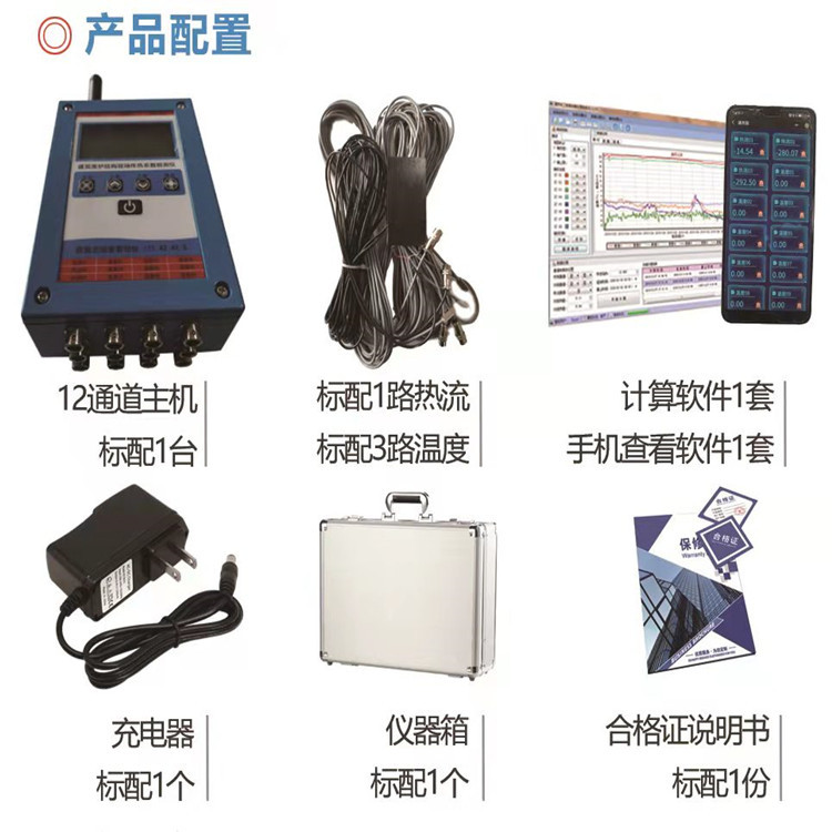
When conducting wall thermal insulation performance tests using the heat flow meter method, install temperature sensors and heat flow meters on the heated side of the specimen.,Sensor Quantity 2Branch, Thermocouple1 pc、 Sample Cold Side,Temperature Sensor1 pc、 Note:The temperature sensor and heat flux film must be in good contact with the specimen.
1.2 Calculation Formula
The thermal resistance and heat transfer coefficient are calculated using the arithmetic mean, as follows:
R=△t/q= (Ti-Te)/(C×E)
K=1/(R+Ri+Re)
R — thermal resistance of the specimen itself; m²·K/W
△ t — Temperature difference between the cold and hot surfaces of the specimen; ℃
q - Heat flow
C - Heat Flow Meter Calibration Coefficient; w/m²·mv
Electromotive force (thermocouple reading); mv
K - Thermal Conductivity; W/m²K
Ri - Heat transfer resistance of the inner surface of the test piece; typically 0.11 m²·K/W for walls.
Re — Heat transfer resistance of the inner surface of the test piece; for walls, generally take 0.04 m²*k/w
2. Laboratory Testing Methods
2.1 Sample Condition Adjustment
To minimize the impact of moisture on the heat flow in the test piece, it is recommended to adjust the test piece to a near-dry state before measurement. Install or construct the test piece within the test piece frame, and then coolThe hot surface is coated with the appropriate paint layer as per customer requirements, such as ceramic aggregate concrete hollow blocks, slag concrete hollow blocks, etc. Both sides must be plastered to prevent air infiltration. When installing the specimens, the edges should be sealed to prevent air or moisture from entering through the edges or from the hot side to the cold side, and vice versa. Measure the points after drying and hardening.
2.2 Sensor Layout
When measuring the surface temperature of the specimen, use an aluminum thin tape to attach the temperature sensor to the hot and cold surfaces of the specimen. Ensure a tight attachment to prevent any gaps.The detection results will be severely affected. Place six sensors evenly on the surface of the specimen, and the temperature sensors for cold and hot surfaces should be symmetrically arranged.
3. Field Test Methods and Precautions
3.1 Field testing equipment includes temperature sensors, heat flow meters, and temperature and heat flow scanners. When measuring a room without heating, the room to be measured should be heated, and electric heaters are recommended for heating.
3.2 Heat flow meters and temperature sensors should be affixed to the inner surface of the protective structure and should be in close contact with the surface; temperature sensors should be mounted on both the inner and outer surfaces of the protective structure, with the inner surface temperature sensors positioned near the heat flow meter, and the two surface temperature sensors should be arranged correspondingly.
3.3 The measurement time is related to the room's heating conditions. In rooms that are pre-heated under non-severe weather conditions, the testing can generally be completed in 4-5 days. Rooms that are not heated require additional heating measures. The data can only be used for calculation and analysis after the room temperature reaches the set temperature and the envelope structure has reached a stable thermal state. Typically, data from the first three days of room heating should not be used.
3.4 During the on-site inspection process, continuously monitor the stability of the data. When approaching or reaching a stable state, the daily collected data can be individually processed.
Alright, for heavy-duty protective structures, the last one...The R value must not differ by more than 5% from the R value 24 hours prior, or the calculated results over consecutive n days must not differ by more than 5% from the R values calculated over the same number of days, at which point the test can be terminated.
3.5 During the on-site inspection process, it is essential to maintain a relatively stable temperature within the inspection unit's room at all times.
3.6 Maintain a significant average temperature difference between indoor and outdoor spaces.
3.7 Maintain the continuity of data collection.
3.8 Preferably select larger exterior wall sections for inspection.
3.9 Measurement points should be as far away from thermal bridges as possible.
3.10 Avoid direct sunlight affecting outdoor temperature measurement points.
4. Hardware Description
4.1 Technical Specifications
Temperature Measurement Range: -55℃ to +125℃
2 Thermal flow measurement range: 0-200mV
Accuracy: ±0.1℃ (10℃ to +85℃)
Resolution: 0.1℃
5 Sample Points: 12 Channels
6 Inspection Cycle: Over 1 minute (adjustable)
Alarm Threshold: -55℃ to +125℃
Transmission Technology: RS485, RF (Radio Frequency), GPRS
9 Measurement Point Line Length: Less than 100 m
10 Power Supply: DC12V
Operating Temperature: -30℃ to +80℃
12 Working Humidity: Less than 90%RH
Cable Protection Class: IP68, IP69K