
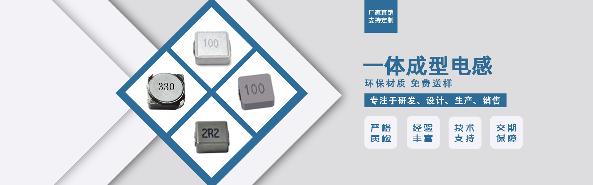


Integrated Molding Inductor - The Rising Star of the Inductor World, Catching Up with the Times, Becoming the Favorite of the New Generation. As technology continues to mature, issues such as cracking are no longer a problem. However, when determining the quality of an integrated molding inductor, skill is still required. First, inductor measurement: turn the multimeter to the diode beeper mode, place the probes on the two terminals, and observe the multimeter reading. If the multimeter reading is significantly high or infinite, it indicates the inductor is damaged. Second, for inductors with more turns and finer wire, the reading can reach tens to hundreds. Under normal circumstances, the DC resistance of the coil is only a few ohms. Damage is manifested as overheating or the magnetic ring of the inductor is visibly damaged. If the inductor coil is not severely damaged but cannot be determined, you can use an inductor meter to measure its inductance or use the replacement method to judge. Additionally, here are some points to note when in use: 1. Inductor components, their cores and windings are prone to inductance variation due to temperature rise effects, so their body temperature must be within the specified usage range. 2. The windings of the inductor, after current passes through, are easy to form an electromagnetic field. When positioning the components, ensure that adjacent inductors are kept apart or the winding groups form right angles to reduce mutual induction. 3. The windings of each layer in the inductor, especially the multi-turn fine wires, can also produce inter-winding capacitance, causing high-frequency signal bypassing and reducing the actual filtering effect of the inductor. 4. When testing inductance value and Q factor with a meter, to ensure accurate data, the test leads should be as close to the component as possible.
News Center Co., Ltd.
