


- AllProduct Category
-
Multi-functional High-Efficiency Decolorizing and Regeneration Oil Filtration Machine
Infrared Liquid Level Controller
Volumetric Oil Injection Machine
Transformer Oil Filtration Machine
Phosphate Antifire Oil
Agglomeration Dewatering Oil Filter Machine
Lubricant Vacuum Oil Filter Machine
Turbine Oil Vacuum Filtration Machine
Pressure Plate Filter Press Machine
Portable Filter Oil Machine
Air Drying Noisemaker
Explosion-proof Vacuum Oil Filtration Machine
Lubricant Filter Machine
Lubricant Filtration Machine
Two-Stage Vacuum Oil Filter
Turbine Oil Filtration Machine
Hydraulic Oil Filter Machine


详情描述
I. Usage and Functions
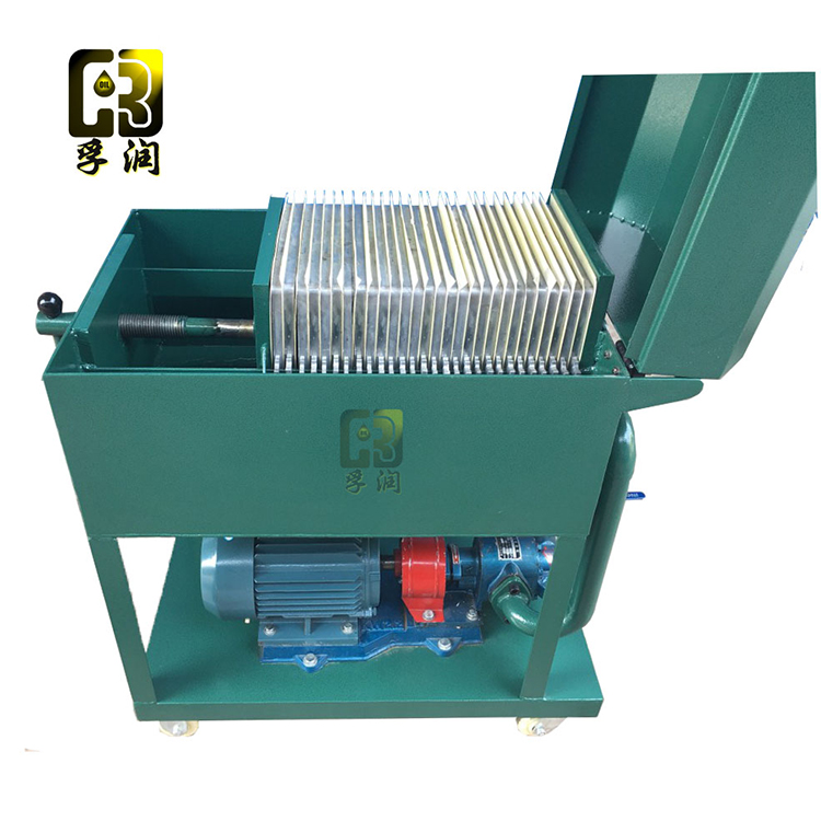
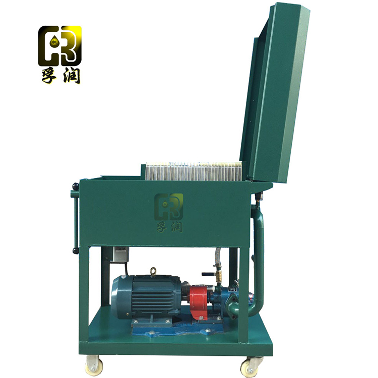
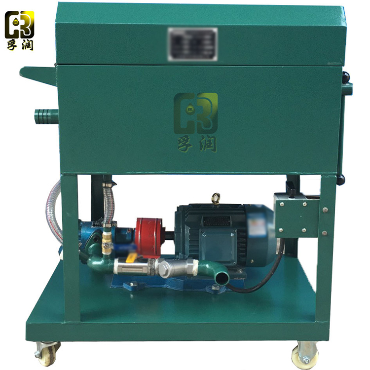
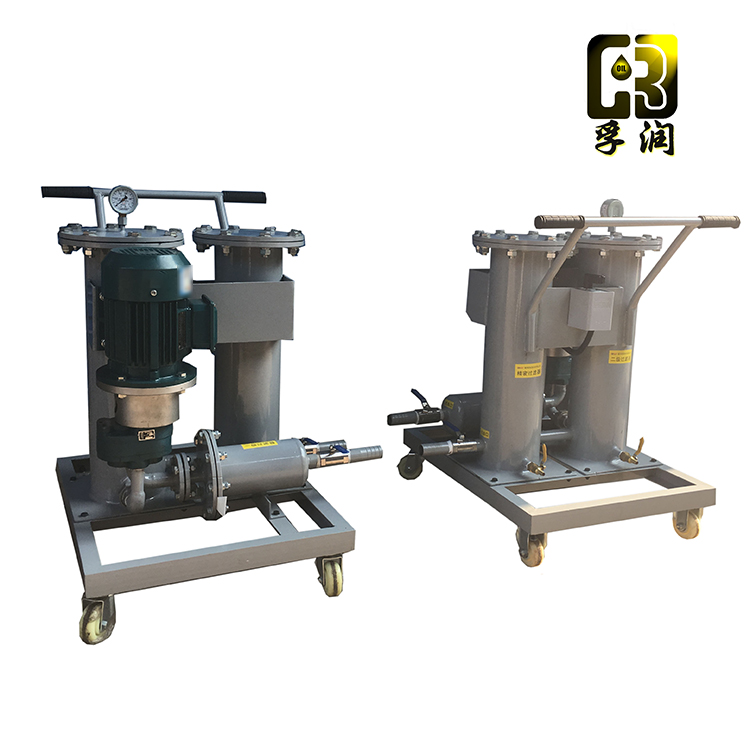
The LY series plate-and-frame pressure oil filter is specifically designed for power plants, power stations, transformer substations in industrial and mining enterprises, lubricant storage rooms, tractor stations, oil and gas, chemical, metallurgical, and other units. It is primarily used for filtering moisture and impurities from transformer oil, turbine oil, aviation hydraulic oil, fuel oil, and other types of oil. The plate-and-frame oil filter consists of filter beds, oil pumps, and filters. Filter paper or filter cloth, serving as the filtering medium, is sandwiched between the filter plates and frames. The plates and frames are secured into a single filter chamber by the pressure from the clamping device. The filter paper or filter cloth compressed between the plates and frames performs the oil filtration function.
II. Cautionary Notes:
Check if the power wiring is correct and if the casing is properly grounded.
2. Ensure the filter plates, frames, and filter paper are properly positioned.
3. Do not apply excessive force when tightening the filter plate; ensure the body is placed flat.
4. Always monitor the pressure and oil tank level when in use. If an abnormal sound from the oil pump is detected, immediately shut down and inspect.
5. After use, clean the residual oil in the case thoroughly and disconnect the power supply.
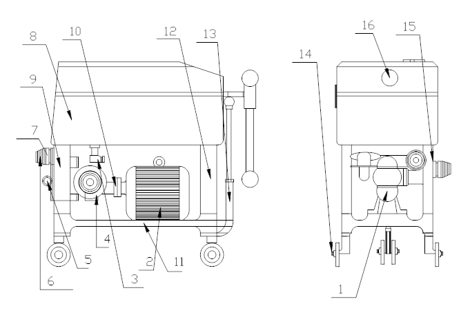
III. Structural Composition
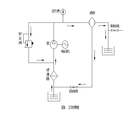
The unit consists of a gear pump (1), a safety valve (5), a return oil valve (3), a drain nozzle (7), a filter bed (8) including a pressure gauge, filter plate, filter paper, filter frame, and oil pan, a front bracket (12), a rear bracket (9), a base (11), a connecting rod (13) with a coupling (10), and an electric motor mounted on the base above the filter bed. The filter is installed on the front side of the gear pump, with a return oil valve fitted to it and connected to the oil pan via polyvinyl chloride piping. The filter bed is mounted on the gear pump and above the brackets. The filter plate and frame (refer to Table 1) alternately form separate filtering chambers, with the filter paper sandwiched between them. The inlet and outlet oil hoses are connected to the inlet and outlet pipe joints (15, 6). The oil to be filtered is drawn in through the filter's inlet port, passes through the filter to remove larger contaminants, and then enters the gear pump. The electric motor, via the coupling, drives the gear pump, exerting pressure on the oil to flow into the filter bed. The filtered oil passes through the filter paper, removing impurities. Due to the capillary action of the filter paper, it can absorb residual moisture in the oil. The filtered oil is then discharged through the oil pipes. The safety valve controls the pressure in the pipeline system; if the oil pressure exceeds the specified value, the safety valve activates immediately, causing the filtered oil to circulate within the pump, preventing further pressure increase to ensure safe operation of the equipment. The return oil valve, utilizing the vacuum effect at the gear pump's inlet, draws oil from the oil pan into the filter. The drain nozzle is used for taking oil samples for pressure and other physical and chemical property tests. The unit features a base with casters (14) that allow it to be moved manually by pulling the connecting rod.
Four: Outline Structure Diagram and Working Principle Diagram
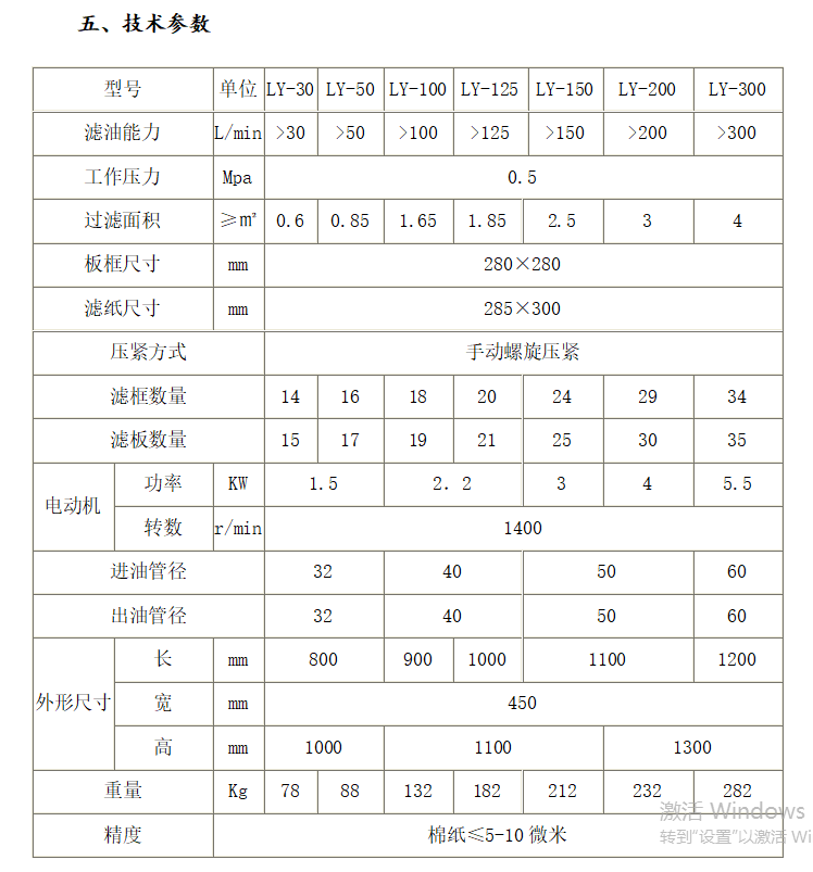
*The appearance, dimensions, and technical specifications of the equipment are for reference only and may slightly vary with the continuous development of the product. Please refer to the actual product.


