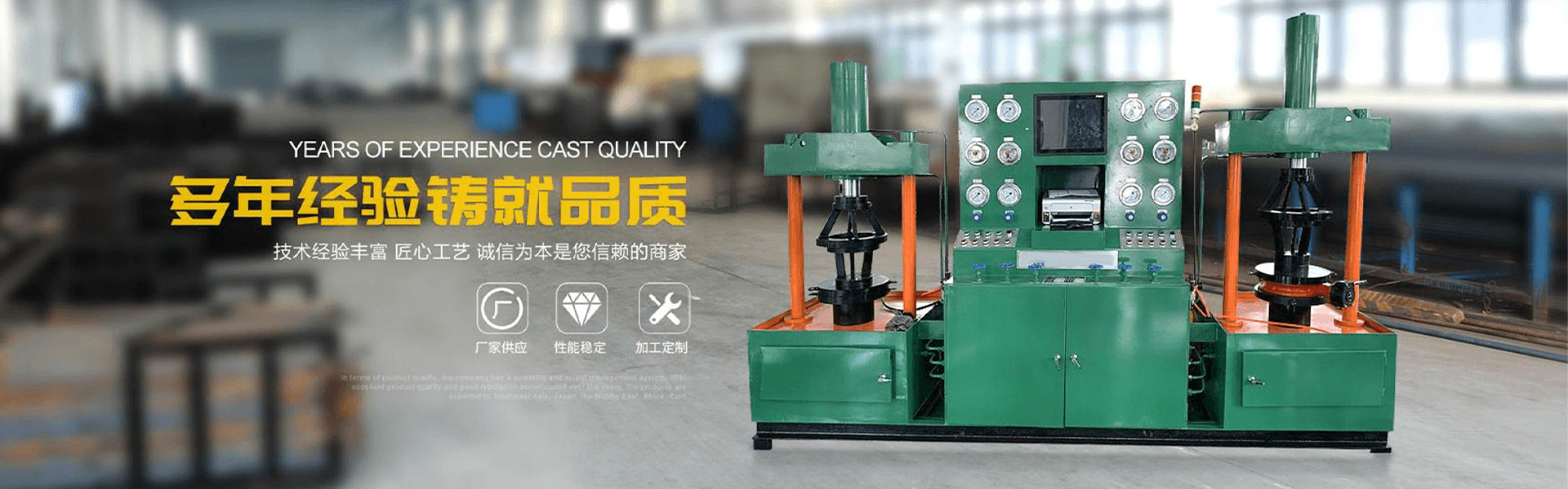

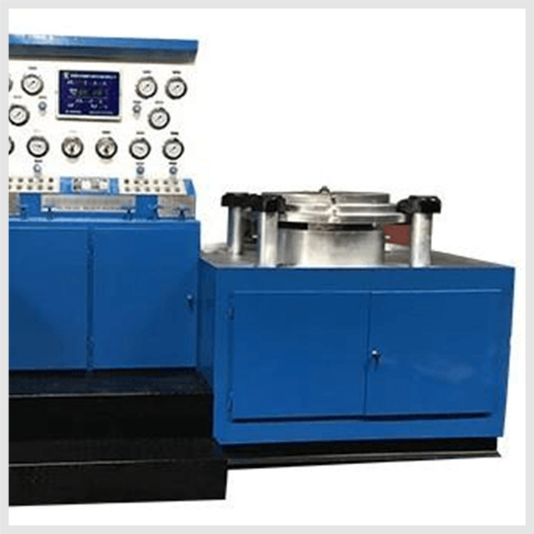
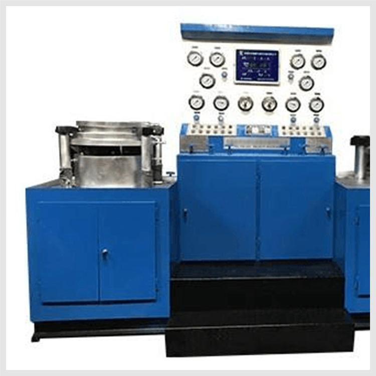

The DYFJ-H600 valve testing bench is the fourth-generation pressure testing and detection equipment independently developed by Duojia Hydraulics on the basis of many years of production experience, in accordance with national standards and specifications.
The DYFJ-H600 valve test bench integrates mechanical, hydraulic systems, pressure testing, and storage and recycling of liquid media. It boasts complete functions, stable performance, and high degree of automation. It is widely used for sealing face leakage testing and other performance tests, such as shell strength (pinhole), of various high, medium, and low-pressure valves with nominal pipe sizes of 50-600mm in straight-through flanged designs. Test media: water, gas, oil.
The equipment is fully driven by hydraulic power and controlled by electrical systems, with no external force affecting the valve's test results, which significantly enhances work efficiency and reduces labor intensity. It is the ideal new generation of valve pressure testing equipment for valve manufacturing companies, users, and maintenance units.
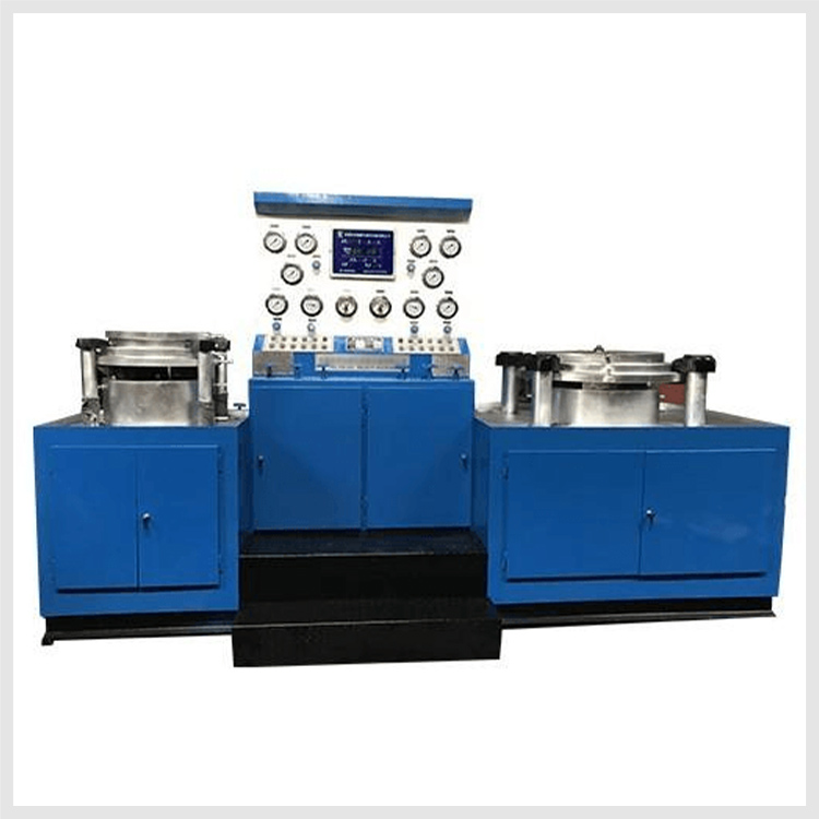
DYFJ-H600 Valve Test Bench Operating Principle and Structure
The DYFJ-H600 valve test bench operates by positioning the valve flange and clamping the back of the flange with movable claws, ensuring no external forces affect the test results, in compliance with national standard valve testing requirements.
The equipment is broadly categorized into hydraulic pressure supply systems, electrical control systems, water circulation systems, and various operating devices.
The equipment is of clamping type, with both sides of the workbench sealed with blind flanges, and the hydraulic clamp has axial extension and radial movement functions, directly driven by a hydraulic cylinder to ensure uniform force on the valve sealing surface and reliable clamping. During the test of the butterfly valve, the sealing performance can be directly observed, facilitating the inspection of air-sealing tests and the observation of the valve sealing surface. It features good performance, simple and compact structure. Operation method:
Valve Mounting Method
Select a valve with a nominal diameter that matches the equipment model, turn on the power, and start the hydraulic system. Move the hydraulic actuating clamp radially to exceed the outer diameter of the test valve flange, and extend the actuating clamp axially to exceed the valve length. Place the lower flange of the valve against the test bench blind plate, aligning with the center hole. Radially move the clamp close to the valve flange, and axially move the clamp to ensure it tightly abuts the valve flange face. At this point, the valve is securely held in place by the clamping system, ensuring it does not wobble.
During the test of the valve body strength, the other end of the valve to be tested is tightly sealed against the upper pressure blind plate, aligned with the center hole. Radially move the clamping jaws close to the valve flange. Axially move the clamping jaws to make the jaws tightly adhere to the back of the valve pressure blind plate. At this moment, the valve should be securely clamped and fixed by the clamping system, with the entire valve in a stable state.
2. Water Pressure Testing Methods (Bi-directional Inflow, Drainage)
After the valve clamp is in place, refer to the "Pressure Requirement Chart for Clamping Cylinders" to increase the gripping force of the hydraulic clamp to the required pressure. Adjust the electrical pressure gauge (for example, with a 25 kg valve, adjust the pointer of the electrical pressure gauge to 2.5 MPa). Open the main water intake, left and right water intake valves, close the air intake, drain, and exhaust valves. Start the low-pressure water pump, observe the movement of the water pressure gauge pointer. When the pointer stops rising, it indicates that the internal cavity of the valve is full of water. Start the high-pressure water pump; the high-pressure water pump automatically stops when the water pressure reaches the pressure set on the electrical pressure gauge, and the equipment enters the water pressure holding state.
Upon reaching the pressure-holding time, the valve is free of any issues. First, open the water discharge valve to relieve the pressure inside the valve chamber, and then remove the valve.
3. Pressure Test Methods (Bi-directional Intake, Venting)
The equipment does not come with a gas source. The user must provide a separate gas source. Please consult the manufacturer before using high-pressure gases.
After the valve fixture is completed (for example, using pressure air, generally not exceeding 10 kg), open the inlet water and air valves, and close the drain water and air valves. Close the inlet water and air valves when the pressure gauge reaches the highest pressure, and the equipment remains in a pressure retention state.
Upon reaching the pressure-holding time, the valve is problem-free. First, open the vent valve to release the pressure inside the valve cavity, then remove the valve.
Cautionary Notes and Requirements
1. Align the equipment horizontally during installation or secure the footings with concrete.
2. Use 46-grade anti-wear hydraulic oil (for temperatures below 0°C, use antifreeze 46-grade anti-wear hydraulic oil). Ensure the oil level does not fall below the indicator. Regularly check the oil level and hydraulic oil. After one year of use, clean the oil tank and replace the hydraulic oil.
3. Add rust inhibitor to the recirculating water, and change the water promptly when the water quality deteriorates.
4. The equipment work surface should be kept clean, and there should be no debris between the test valve flange and the pressure test blank.
5. Add lubricant to all moving parts of the test bench to ensure clean and smooth operation.
6. Operators must undergo professional training before starting work, adhere to standardized procedures, and prioritize safety.
