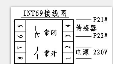
INT69 Thermal Leak Protector Wiring Diagram
Motor thermal leakage protector price
INT69AC220V5A
Submersible pump control cabinet protector
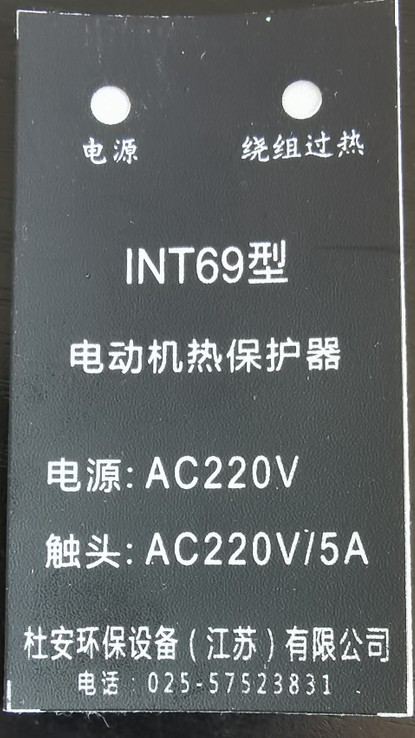
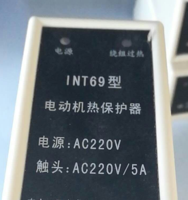
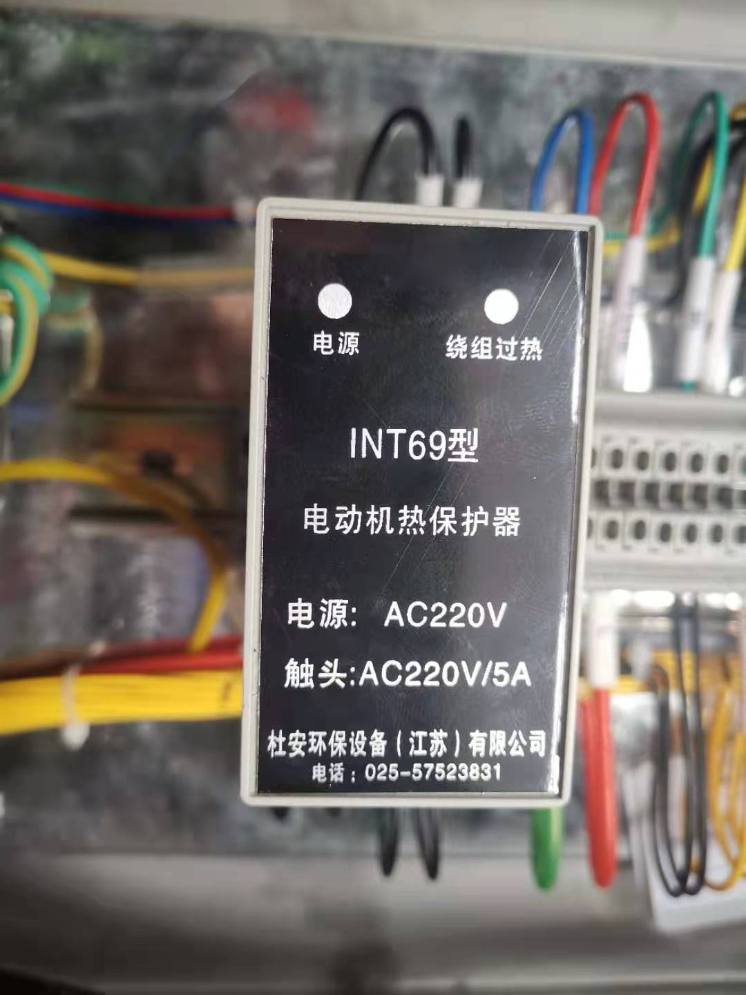
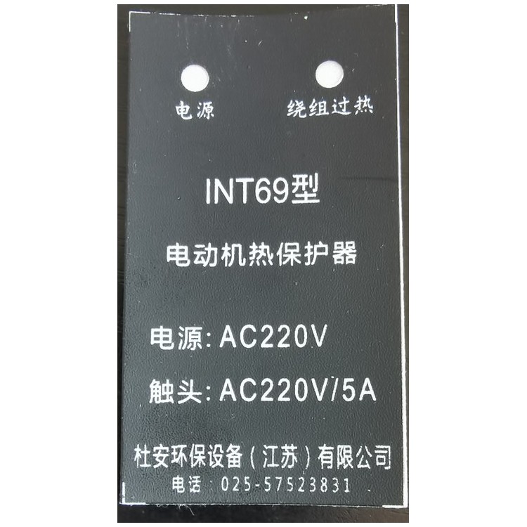
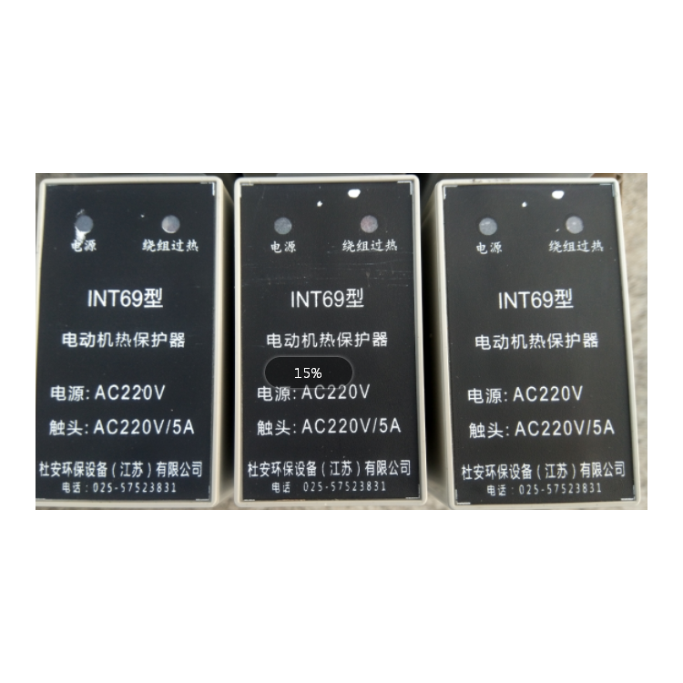
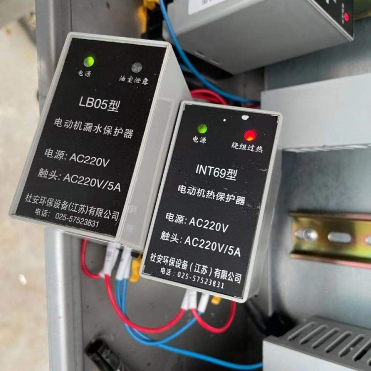
Duwan Eco-Protect INT69 Motor Thermal Protector
Input Voltage: AC 220V ±5%, 50Hz, rated power consumption less than 5W.
Ambient Temperature: -20℃ to 75℃.
Ambient Humidity: Less than 90% (no condensation of water droplets).
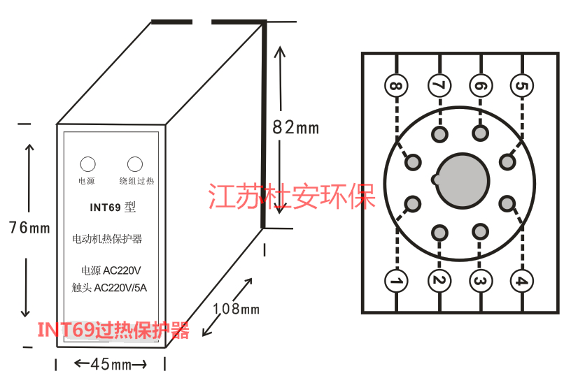
Dimensions: 48 x 80 x 120, Weight: 0.3 Kg.
Installation Method: DIN35 track mounting.
Principles and Solutions for Motor Overheating: I. Motor overheating during no-load operation:
One,Reason: 1,Stator winding resistanceConnection Error (e.g., connecting stars in a triangular shape) Connection method. Handling method: Verify wiring method.
2. The voltage is too high.
Method of Handling: Inspect Main Power Voltage
3. Inability to cool due to blocked ventilation channels.
Remediation Method: Eliminate ventilation channel obstructions.
4. Fan rotation direction is incorrect (motor designed for one-way rotation). Solution: Verify the fan and its rotation direction.
2. Overheating under motor load
Reason 1: Electric MotorOverload.
Procedure: Verify current, reduce load as needed.
Reason 2: Voltage too high or too low.
Method of Handling: Verify voltage.
Reason 3: Single-direction motor operation.
Method of Handling: Trace and address the disconnection point of the incoming line.
Reason 4: Stator and rotor rubbingInsufficient coolant flow or localized blockage.
Process: Check air gap, adjust water pressure, water volume, and exhaust.
Section 3: Local Overheating of Stator
Reason: Stator winding short circuit (some coils overheat and produce a humming sound).
Treatment Method: Identify and treat the short-circuit winding.
Motor Overheat and Overload Protection Device Precautions
1. Motors are more prone to burn out their windings than in the past. This is due to the continuous advancement in insulation technology, which demands that motor designs increase output while reducing size, resulting in newer motors having less thermal capacity and weaker overload capabilities. Additionally, with the increased level of production automation, motors are often operated under frequent starts, stops, reversals, and variable loads, placing higher demands on motor protection devices. Moreover, motors are used in a wider range of applications, often in harsh environments such as dampness, high temperatures, dust, and corrosion. Coupled with irregularities in motor manufacturing and lapses in equipment management, all these factors contribute to the current trend of motors being more susceptible to damage, especially with higher frequencies of overloads, short circuits, phase loss, and shaft erosion.
2. Traditional protective devices do not offer ideal protection, as they primarily rely on fuses and thermal relays. Fuses are mainly used for short-circuit protection, and the selection of fuse current must consider the motor's starting current, making it impractical to use fuses for motor protection alone. Thermal relays are widely used for motor overload protection, but they have low sensitivity, large errors, and poor stability, resulting in unreliable protection. This is indeed the case, as despite many installations of thermal relays, motor damage affecting normal production still occurs frequently. There are no products on the market yet that can achieve mechanical wear monitoring of motors and eccentricity monitoring of stators and rotors with traditional protective devices.
3. Motor protectors have evolved from mechanical to electronic and intelligent types, featuring high sensitivity, reliability, multiple functions, and easy tuning. They can directly display parameters such as motor current, voltage, and temperature. The fault type after protection action is clearly visible, greatly facilitating fault diagnosis and beneficial for on-site troubleshooting in production environments, as well as reducing the time to resume production. Additionally, the technology for detecting motor eccentricity based on the air gap magnetic field allows for online monitoring of the motor's wear status. The curve display reflects the changing trend of values indicating the degree of motor eccentricity, recording the variation of this value over two years. This enables early detection of bearing faults, achieving early discovery and early treatment to prevent扫膛事故 (bearing failure).
3. The purpose of selecting an electric motor protection device is to enable the motor to fully utilize its overload capacity while avoiding damage, as well as to enhance the reliability of the electrical drive system and the continuity of production. A simple protection device should be considered first as long as it meets the protection requirements. Only when a simple device fails to meet the requirements or when higher protection functions and characteristics are demanded, should a complex protection device be applied, achieving a balance between economy and reliability. The specific functional selection should be based on a comprehensive consideration of factors such as the motor's intrinsic value, load conditions, environmental quality, the motor's importance, and the impact on the production system if the motor is taken out of service, with the aim of achieving economic rationality.
4. The ideal motor protector is not just a functionGood in quantity, not necessarily cutting-edge, but more practical. Practicality should meet factors like reliability, economy, and convenience, with a high performance-to-price ratio. What does reliability entail? First and foremost, it should ensure the reliability of the function, such as the overcurrent and phase-loss protection functions must reliably activate in response to overcurrent and phase-loss events under various conditions, processes, and methods. Secondly, the reliability of the device itself (since protectors are meant to protect others, they should particularly have high reliability) must possess adaptability, stability, and durability in various harsh environments. Economy: Utilizing advanced design, reasonable structure, specialized, and large-scale production reduces product costs, offering users high economic benefits. Convenience: It must be as simple and convenient as possible in installation, use, adjustment, and wiring.
Installation and Usage Precautions
When using contact-type temperature sensing installation, the product should be pressed tightly against the installation surface of the controlled device.
2. Do not crush or deform the plastic or metal housing during installation to avoid affecting performance.
3. For metal shell products with added insulating sleeves, do not remove or crush the external insulating sleeve during installation, to prevent electrical leakage and ensure safe use.
4. When used in circuits with currents not exceeding 5A, copper-core wires with a cross-sectional area of 0.4-0.75 mm² should be chosen for connection.
5. Products should be stored in a well-ventilated, clean, dry, and non-corrosive gas-free environment with a relative humidity below 90% and a temperature of 40℃ or below.
Cardboard packaging, containing product manual, certification of compliance, and product circuit diagram.