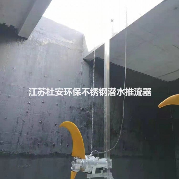

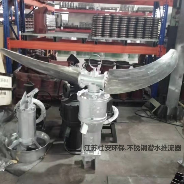
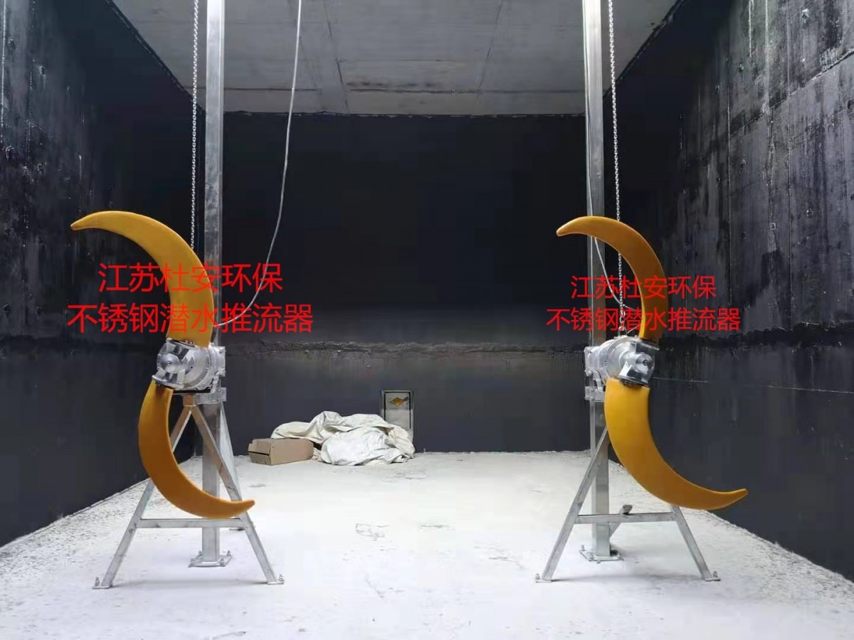
Diving Propeller - 304 Stainless Steel Material
Duwan Environmental Protection 304 Stainless Steel Low-Speed Turbulator
Impeller diameter: 1800mm
Gearbox reducer
Duwan Environmental 304 Stainless Steel Submersible Propeller Flow DriverKey Components
(1) Fully Assembled Submersible Propeller
(2) Accompanying diving motor;
(3) Complete installation system (guides, brackets, cable tensioners, etc.)
(4) A set of lifting equipment (including portable lifting supports, lifting pulleys, stainless steel lifting chains, and hooks, etc.).
(5) Submersible cable for each streamer
(6) Flow protector components include leak protection, temperature protection, and protection controllers, etc.
(7) All connecting accessories, all fasteners required for installation (including stainless steel anchor bolts, nuts, washers, etc.).
(8) Two years of spare parts and accessories during the warranty periodBackupTools.

Duwan Eco 304 Stainless Steel QJB Submersible Propeller Flow DriverPerformance and Structure:
1、DivingStream Driver Structure
(1) Construction of Low-Speed Turbulator
Each flow regulator should be equipped with a gearbox and have a submersible enclosed connection design. All components of the flow regulator, including the motor and gearbox, should be capable of continuous underwater operation. The main components of the flow regulator that come into contact with liquid should be made of stainless steel. AISI 304. All nuts, bolts, and washers should be made of AISI 304 stainless steel or better material. The oil chamber cover should be made of a corrosion-resistant synthetic material. On critical contact surfaces requiring waterproof sealing, use nitrile or fluorinated rubber O-rings to ensure that the rubber O-rings on both surfaces and the four sides of the O-rings contacting each other can be tightened without special torque limitations. Forms requiring a certain torque to achieve tightness are not allowed, and those requiring a certain rectangular cross-section washer and sealing compound are also to be disregarded.
The flow inducer should be capable of handling raw and wastewater. The flow inducer is adjustable vertically, making it easy to move for inspection or maintenance without needing personnel to enter the wet well. The sliding rod bracket is one of the integral components of the flow inducer. All the weight of the flow inducer is supported by a single bracket, which must be able to withstand the thrust formed by the flow inducer.
All mechanical seal surfaces should be made of corrosion-resistant tungsten carbide or better materials. The service life of mechanical seals should not be less than 25,000 hours.
Flow controllers and their accessories, as well as cables, should be capable of continuous immersion in deep depths of 20 meters underwater without losing its watertightness (compliant with IP68 protection rating).
(Propeller
The propeller should include two glass fiber reinforced polyurethane blades, each equipped with a stainless steel shaft mounted in an iron wheel hub. The blades should haveFlexible and capable of absorbing changing hydraulic loads. Metal blades are not acceptable due to their lack of elasticity. Each blade should be mounted in a socket on the hub side and secured in place by a keyed propeller shaft to resist torque. The propeller shaft should be axially fixed to the hub and a locking washer system should be used.
The blade shape should be a non-blocking, swept design, originating from the hub, ensuring no part of the shaft is exposed. The propeller should be capable of handling particles, fibrous materials, heavy sewage, and other substances encountered in conventional wastewater treatment.
The propeller should pass dynamic balancing inspection.
(3) Gearbox
The gear box should be a two-stage, cylindrical helical gear box equipped with high-precision, low-load gears. The motor shaft should be fitted with an integrated drive gear. The intermediate shaft of the gear box containing the first-stage drive gear should be tightly matched with the drive gear of the motor shaft. The intermediate shaft should rotate in two roller bearings and contain a second-stage drive gear. The impeller shaft should include a second-stage drive gear and rotate in a single-row and a double-row angular contact ball bearing.
(4) Axle
Motor shaft and propeller shaft are connected through a gearbox; the shaft is made of stainless steel. 431 Manufacturing: Prop shaft and motor shaft can withstand all axial and radial loads. The prop shaft is fully protected by mechanical seals and radial seals, isolated from the liquid.
(5) Bearings
The flow meter motor shaft should rotate on two lubricated bearings. The inner bearing should be a single row deep groove ball bearing, while the main bearing is a double row roller bearing. All bearings are high-quality, maintenance-free units lubricated with grease, capable of withstanding axial and radial loads. The design life of all bearings is at least 100,000 hours.
(6) Electric Motor
The pump motor should be a squirrel-cage induction motor, housed in an inflatable, waterproof casing. The stator windings and wires should be insulated to resist moisture, with an insulation grade of H (180℃). Additionally, a colored printed product sample with the manufacturer's seal confirming authenticity or other proof materials should be provided.
The stator should be insulated by the injection method to ensure the winding is fully charged at least. 95%. The stator should be heat-shrink fitted into the cast iron stator chamber. The motor should be designed to continuously handle a 40°C flow medium, and capable of starting at least 30 times per hour with uniform intervals. The thermal switches should be set to activate at 125°C and be embedded in the stator windings to monitor the temperature of each phase winding. These thermal switches should be used in conjunction with the external motor overload protection as a supplement to it, and should be connected to the electrical control cabinet.
The motor and the impeller should be provided by the same manufacturer. The allowable voltage fluctuation for the motor is+/-10%, the motor is designed to operate in a higher 40°C environment, with the average temperature rise of the stator windings not exceeding 85°C. A performance chart that displays torque, current, power factor, input/output power, and efficiency should be provided. The chart should also include data for startup and zero-load characteristics. The motor and cable should be capable of continuous underwater operation, with a watertightness that meets IP68 protection class requirements. The rated power of the motor should be sufficient to ensure that the propeller does not overload throughout the performance curve.
Monitor cables should include two cores 1.5mm 2-core wire, used for connecting thermal switches and optional protective sensors.
(7) Mechanical Seals
Each impeller should have an oil chamber for the shaft sealing system and an independent second oil chamber for the gearbox. The drain and inspection plug should be easily accessible from the outside. Each impeller should be equipped with a triple seal to separate the various parts of the impeller. The external seal on the impeller shaft should be a mechanical seal containing a corrosion-resistant sintered tungsten carbide ring with one stationary and one forward-drive rotating portion. The seal should operate in an oil chamber that lubricates the overlapping sealing surfaces at a constant speed through hydraulic action. Only the external seal's sealing surface can be exposed to the impelling fluid.
Mechanical seals are made of corrosion-resistant sintered tungsten carbide material and feature an active sealing structure. Provide material certification and a colored printed product sample with the manufacturer's seal confirming authenticity, or other proof materials.
The inner seal on the impeller shaft should be a nitrile rubber lip seal, separating the impeller shaft oil chamber from the gearbox oil chamber. The three seals should be a single nitrile rubber lip seal mounted on the motor shaft, isolating the gearbox oil chamber from the stator chamber. The seals should neither require maintenance nor adjustment and should not be dependent on the rotation direction.
Medium pH range should be 4 to 10.
The design service life of the mechanical seal should exceed 25,000 hours.
(8) Cables and Cable Seals
The cable entry room should be a complete unit with a fixed plate. There should be two sets of elastic bushings at the cable entry to ensure water and submersion sealing. A single sealing system will not be used. The cable entry should include two cylindrical elastic bushings, each equipped with a washer and a collar. They should have precise tolerances to fit the cable's outer diameter and the entry's inner diameter. The bushings can be compressed by a sealing tube, which is secured to the cable entry room with two stainless steel screws. Sealing should not be achieved by torque rotation but rather by the interaction between the sealing tube and collar, moving the bushings along the cable's axial direction. The design is rational and allows for quick disassembly and maintenance.
The switchgear room and motor room should be isolated by a junction plate to protect the motor and prevent external substances from entering through the top of the blower. The junction plate will be securely fastened with a threaded type, and the cables can be safely connected to the junction plate. The junction plate will be equipped with two The O-ring isolates and seals the stator chamber; it cannot be sealed with epoxy, silicone resin, or other secondary sealing systems.
The motor should be equipped with a submersible cable, which should be a single cable incorporating both control and power cores. The dimensions and quantity of the power cores and control cores must be sufficient to ensure normal operation, control, and monitoring. The dimensions should comply with: IEC standard, with sufficient length to connect to junction boxes or local control cabinets without splicing (not less than 10m in length). The cable outlet is arranged axially, aligned and tightly mounted to the outer surface of the motor housing. It is also secured with cable clamps and tension cables to prevent movement due to water impact and to avoid snagging during lifting.
(9) Motor Protection
All stators should be equipped with three series-connected normally closed thermal sensors to monitor the temperature of each stator coil. When the temperature is high, the sensors will disconnect, causing the motor to stop rotating and emit an alarm signal.
2.3.5 Stream Encoder Performance
DivingThe flow regulator must be submersible and horizontally installed; other types of flow regulators are unacceptable. The flow regulator should be adjustable for up and down movement, easily movable, and should allow for easy disassembly for inspection or service without requiring personnel to enter the pool or well.
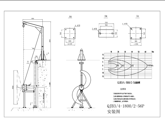
The submersible propeller should be a complete set, including the installation system and lifting device. The installation system should consist of square steel guide rods, top and bottom supports, etc., allowing for free adjustment of the propeller's lifting and lowering, and the propeller can be disassembled and installed without emptying the pool. The propeller is mounted on a bracket that slides on the guide rod as a unit, which must be capable of supporting the entire weight of the propeller and all the forces exerted. The lifting device should be portable, and the hoist's fixed device should not be installed on the pool wall or poolside work platform, but on the top support of the installation system, and should include a hoist hook, lifting chain, and pulley. Each propeller is equipped with a hoist set.
Each streamer should be supplied with a cable net sleeve to prevent cable damage caused by fluctuations in the streaming flow.
All lifting arms equipped with mounting brackets and lifting devices should be AISI 304 stainless steel material. The lifting chain should be made of AISI 304 stainless steel. Bolts, nuts, washers, rotating operation handles, and anchor bolts should also be supplied as a set. Chemical bolts must be used for the installation of anchor bolts to ensure a sturdy and durable installation of the flow controller system, as expansion bolts are not allowed.
Submersible flow distributors should be capable of adapting to the corrosive environment of municipal wastewater. They must be able to propel the wastewater or sludge flow, ensuring bottom velocity in the pool (from the bottom of the pool). The flow rate should not be less than 0.3 m/s (with a standard of 300mm). The pump should operate continuously under full immersion conditions. It should also be capable of adapting to continuous operation, intermittent operation (the number of starts per hour should be able to reach 20), and the ability to resume operation after a long period of shutdown.

Stainless Steel Diving EquipmentThe pump must operate smoothly without vibration. All rotating parts (including the motor) should undergo dynamic and static balance tests during manufacturing. The pump should be cost-effective for maintenance, highly reliable, and operate without failure for a long duration.
Diving Propulsion DeviceMain components material:
Propeller: Glass fiber reinforced polyurethane
Mixer housing: Grey iron casting ASTM A-48 Class 35B
Axle: Stainless Steel 431
Mechanical Seal: Corrosion-resistant Sintered Tungsten Carbide
Fasteners: Stainless Steel AISI 304
Cable jacket: Chloroprene rubber
O-ring: Nitrile rubber or fluororubber
Flow Rate Mount: Stainless Steel AISI 304
Track System: Stainless Steel AISI 304
Enhanced Steel Wire: Stainless Steel AISI 304
Hoisting arm lifting device: stainless steel AISI304
Chemical Foot Bolt: Stainless Steel
Surface Corrosion Protection: Two-component epoxy resin coating, two layers of primer, each with a thickness100m, finish paint thickness 120m.
Diving Propulsion System SetOn-siteStainless SteelControl Box
The on-site control box for the supplied equipment should be cutting-edge, proven safe and reliable in actual operation, and meet all design specifications, while conforming to general technical requirements of electrical drawings.
Each set of dive propulsion vehicles comes with a local control box.
Stainless SteelField control cabinet requirements are as follows:
(1) Equipped with internal buttons and signal lights, all control boxes have signal lights unified as red for stop, green for operation, yellow for fault, and blue for power indication.
(2) Purchase the conversion unit for motor protection and match it with the equipment for ordering.
(3) The start/stop button should have two sets of contacts, and the emergency stop button (with a mushroom head) should remain engaged when pressed.
(4) Terminals use wiring terminals.
(5) With cable connectors.
(6) Protection Level: IP65.
(7) Reserve PLC interfaces; each unit requires control from both the local control cabinet and the central control room.
(8) A 3P-32A circuit breaker must be installed and wired within the site control line for the owner's future maintenance of temporary power connections.
(9) The control box should have cooling louvers on both sides and a cooling fan installed at the bottom.
Dive PropellerAttachments and materials
Two-year warranty for spare parts with normal operation within the warranty periodInventory List;Configuration parameters; flow field diagrams; selection reports; rod efficiency verification; equipment dimension drawings; main equipment characteristics; performance guarantee letters, and other related documents.
Jiangsu Du'an Environmental Protection QJB Submersible Turbulator Model Specifications:
Stream Controller Model | Power | Current | Impeller diameter | Thrust | Weight | Install the system |
KW | A | mm | N | kg | ||
QJB1.5/4-1100/2-85P | 1.5 | 4 | 1100 | 1800 | 170 | SystemⅣ |
QJB1.5/4-1400/2-36P | 1.5 | 4 | 1400 | 800 | 175 | SystemⅣ |
QJB1.5/4-1800/2-42P | 1.5 | 4 | 1800 | 1480 | 180 | SystemⅣ |
QJB2.2/4-1400/2-42P | 2.2 | 5.3 | 1400 | 900 | 180 | SystemⅣ |
QJB2.2/4-1800/2-42P | 2.2 | 5.3 | 1800 | 1100 | 185 | SystemⅣ |
QJB3/4-1100/2-115P | 3 | 7.2 | 1100 | 2200 | 180 | SystemⅣ |
QJB3/4-1400/2-56P | 3 | 7.2 | 1400 | 2000 | 185 | SystemⅣ |
QJB3/4-1800/2-56P | 3 | 7.2 | 1800 | 1800 | 190 | SystemⅣ |
QJB4/4-1800/2-56P | 4 | 9.2 | 1800 | 1700 | 170 | SystemⅣ |
QJB4/4-1800/2-63P | 4 | 9.2 | 1800 | 1800 | 190 | SystemⅣ |
QJB4/4-2500/2-42P | 4 | 9.2 | 2500 | 2900 | 210 | SystemⅣ |
QJB5/4-2500/2-56P | 5 | 11.9 | 2500 | 3100 | 240 | SystemⅣ |
QJB7.5/4-2500/2-63P | 5 | 15.2 | 2500 | 4250 | 280 | SystemⅣ |