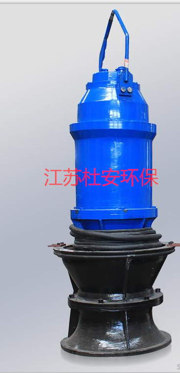
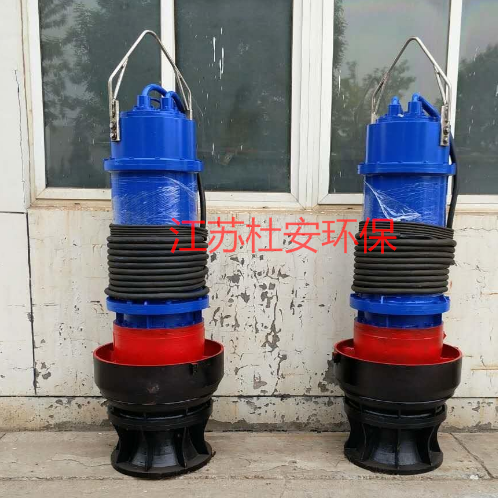
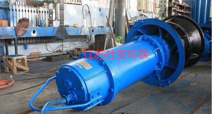
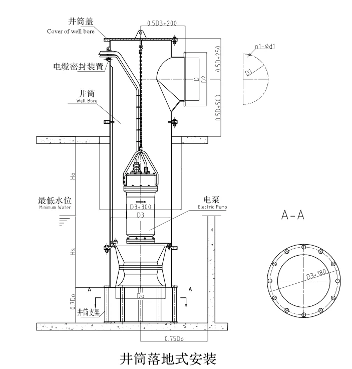
Submersible Axial Flow Pump 350ZQB-70 Installation Dimensions
One, Product Supply Range
Our supply range includes all main units for submersible off-axis flow pumps, as well as all necessary accessories, fasteners, protectors, etc., required for the safe, effective, and reliable operation of the equipment, including but not limited to submersible power cables (compliant with installation distance and requirements).Complete Guiding Rod Elevator System (including stainless steel lifting chains)Cast Iron Drain ConnectorPump handles and buttonholes, etc.The supply.
In addition to the portable submersible sewage pump,Each submersible centrifugal pump is automatic coupling type, comes with a leak protection and over-temperature controller. The anti-seepage and over-temperature control modules are installed in the field button box provided by the electrical equipment supplier.
Each pump should be supplied with the necessary accessories, fasteners, spare parts, protectors, and submersible cables for safe, effective, and reliable operation.
Key Equipment Supply List:
No Chinese content provided. | Name | Specs | Unit | Quantities | Installation Location |
1 | Submersible Axial Flow Pump | Q=230L/S;H=3.0m,N=15.0kW, | Tai | 3 | A2OBiochemical Pond Water Well |
II. Reference Standards
Equipment quality standards, testing procedures, and implementation specifications, etc., are in accordance withISO、IECInternational Standards orAISI、ASTM、AWWAStandard orGB、SL、DL/TStandard Compliance: Bidders must obtain the owner's consent when adopting other equivalent standards to the aforementioned ones.
III. Performance and Main Technical Parameters
Work Conditions:
Medium Conditions
Medium Temperature:0℃~30℃
Medium pH Level:PH:6-9
Environmental Conditions:
Ambient Temperature:3.2~36.4℃
Other
Each pump requires an accessory that is no smaller than10The lift chain of the Mi (meets the usage requirements) should be capable of supporting the total weight of the pump.2Please provide the Chinese content to be translated.Material made for wear and corrosion resistance.
Other operating conditions of the pump should be within the pump's performance curve.
Technical Requirements
Performance Requirements:
The basic design operating point of the pump should be near the rated point, installed within the pump pit, continuously.24Hourly long-term20mDeep underwater operation, capable of intermittent operation or normal startup after extended downtime, with a minimum safe operating time of10000Hour.
Within the scope of design, the submersible pump should operate smoothly without vibration and cavitation, and the motor must be equipped with at least8%Our power reserve.
At rated operating conditions, head, efficiency,NPSHValue deviations should be metISO2548OrISO9906Standard.
Submersible pumps can freely pass through diameters of at least100mmSolid particles, as well as long fiber-like materials.
Mechanical requirements:
Hydraulic Components
The pump's motor and hydraulic components must be products manufactured and supplied by the same manufacturer. The pump should utilizeVertical coupled submersible pump. The submersible motor is directly coupled to the pump impeller, with hydraulic components including the pump housing and impeller.The wheel and the wear-resistant ring are composed of.
The guide string's setup ensures smooth guidance of the pump from the top of the pump well to the outlet connection flange, facilitating disassembly and maintenance. Conveniently, the pump can be automatically coupled to the connection device on the outlet elbow when in place, with the coupling surface of the pump unit mating with the drainage connection socket.The seal should be reliable and completed simultaneously with the descent, without the need for workers to enter the pump room.
The pump casing should be extremely sturdy and robust, securely fastened to the bottom plate of the pump well via an outlet support bend.
Propeller
The impeller design must meet the requirements for non-clogging operation. In terms of hydraulic design, the impeller should integrate forward propulsion and centrifugal force.The impeller's flow line design should be gradient, and the impeller should be a self-cleaning, swept-back impeller with a diameter not less than...φ85mmThe solid particle capability ensures that the impeller will not clog during the conveyance of conventional municipal wastewater and sludge.
Propellers should undergo static and dynamic balance testing; the dynamic balance accuracy should not be less thanIS01940No Chinese content provided.G6.3Please adhere to the strict requirements.
Motor
The motor of the pump should be a squirrel-cage induction motor. The insulation grade of the stator winding and stator connection should beFNo Chinese content provided.155℃ The stator needs to be immersedFInsulating varnish of three grades. Stator applications are embedded in the stator chamber using the shrinkage method. The motor should be designed to be operational at pumping temperatures of40Medium temperature rise does not exceed ℃.80Under ℃ conditions, the pump operates continuously. The pump start-up method is designed for full-load direct start, and should be able to start up on average every hour.12No Chinese content provided.
To monitor the temperature of each winding phase, a thermosensitive switch must be installed within the stator coil.≤70℃ Frequently Closed130The thermal switch needs to be connected to the motor overload protection and wired to the control cabinet. The junction box should include a terminal board. The terminal board should be elastic.OForm rings and motor seals. The junction box should be permanently fixed and connected to the cable conductors and stator input using a wire clamp rod. The pump and motor should be manufactured by the same manufacturer.
Comprehensive work factors(The combined effect of voltage, frequency, and density)At least for1.15The motor's allowable voltage fluctuation is ±10A performance chart should be provided, which displays torque, current, power factor, input/output power, and efficiency. This chart also includes data on startup and no-load characteristics.
The motor should be capable of operation underwater.20The motor should have sufficient shaft power to ensure the pump does not overheat during operation across its entire performance curve.
The entire rotor component must undergo static and dynamic balance tests during the manufacturing process, with the accuracy not to be less thanIS01940G6.3Level requirements. The vibration intensity should meetISOl0816-3,4RegionBNo Chinese content provided.
The motor should allow for a voltage deviation range of±10%Please provide a performance chart that displays torque, current, power factor, input/output power, and efficiency. This chart should also include data on startup and no-load characteristics.
Submersible motors must ensure continuous operation, intermittent operation, and recovery from a long-term stop after being exposed to the surface of the liquid.Operation underway.
The motor should be capable of operation underwater.20mMaintains its waterproof properties with continuous use.
The motor should have sufficient shaft power., Ensure that the pump is maintained throughoutH-QAt any point within the performance curve, the operation runs without overload.
Cooling System: The motor should be capable of obtaining sufficient cooling through the surrounding environment and the medium it pumps, without the need for an additional cooling system.
Bearings (used)NSKOr equivalent.
Utilize high-quality, lifetime lubricated bearings, with a design lifespan exceeding100,000hThe bearings we design must be capable of withstanding all axial and radial loads.Completely separate from the pumping flow.
Mechanical Seals(Axial Seals)
The upper sealing unit placed between the oil cavity and the motor room should be corrosion-resistant (with a pH range ofpH5~10Silicon carbide composition or sintered tungsten carbide composition.
The lower sealing unit, placed between the pump housing and the oil cavity, should be corrosion-resistant (with a pH range ofpH5~10Silicon carbide composition or sintered tungsten carbide composition.
Utilizing two independent high-quality mechanical seal systems, with the lower seal separated from the blade hub and sealed in oil.In operation, the oil cavity can lubricate overlapping sealing surfaces with a stable flow rate, without affecting or losingIn the case of the sealing function, it can be rotated clockwise or counterclockwise without any adverse effects. If the top and bottom seals...Leakage has caused liquid to enter the stator chamber, but it does not contact the lower bearing or the stator.
Each pump should be equipped with a sealed system that is串联 and consists of two separate sealing devices.The shaft sealing system of Tai Pump has an oil chamber, which should be designed to prevent overfilling and accommodate oil expansion.The space, exhaust pipes, and inspection ports must have reliable oil-proof seals and be installed in locations that are easy for maintenance.
Mechanical seals should be maintenance-free and not rely on rotational direction for sealing. Each sealing surface should have a proper contact force.All are completed through their own spring systems.Unable to provide translation without the Chinese content. Please provide the text you would like translated.Ensure even distribution. The lubrication should be isolated from the conveyed liquid, capable of withstanding thermal shock, and exhibit good emergency operation performance.Features.
Contractors must ensure that the working life of the mechanical seals is not less than30000Work Hours.
Mechanical seals must be of Bogemann or equivalent and above.
Pump shaft
Pump and motor shafts should be a single unit. The pump shaft should be an extension of the motor shaft. Coupling arrangements are not permissible. The material of the pump shaft should beAISI420Type 304 stainless steel.
Lubricant
The lubricating oil used must be low viscosity and water-insoluble, and must comply withFDA172、878White Tallow Oil Lubricant meeting hygiene standards, free of aromatic hydrocarbonsFDA172、878The product has been processed in accordance with health standards and is provided with its label model and.../Or alternative label model forPlease provide the Chinese content for translation.
Cables and Cable Seals
The motor should be equipped with underwater cables for control and power, and the cable entry seal design should be capable of eliminating certain torque. To form a waterproof diving seal. To prevent the sealing from being affected by the cable stretching and deforming under tension, a securing device should be used to clamp the cable above the waterproof cable seal, with all the applied tension directed towards the latter.
Each cable has a separate import and is reliably sealed; if the power cable is a multi-core cable, Each cable must undergo individual sealing.The motor features an elastic bushing at the cable entry, compressed with a sealing cover to ensure water resistance and watertightness. The elastic bushing should have precise tolerances to accommodate the cable's outer diameter and the entry's inner diameter. The water-resistant cable entry is protected against tension and tangles, with each line sealed.
Cables and cable entries should be tightly integrated, with the seal designed for ease of cable replacement.
Pump Housing
The pump housing should consist of a diffuser and a trumpet-shaped inlet.
The support face of the expander should be conical, forming a good seal with the conical coupling ring. The pump housing should be cast from high-strength cast iron, with a smooth and unobstructed inner surface. All hydraulic flow components should be designed without sharp angles to ensure a gradual change in flow rate and direction.
Adjustable impeller blade mechanism (if applicable)
Axial flow pump impeller blades can be adjusted to accommodate different on-site working conditions.
Abrasion Ring
To ensure effective sealing between the casing and impeller, wear-resistant rings are installed. These rings consist of a stationary ring mounted at the casing inlet or a rotating ring mounted on the impeller outlet.
The wear ring system should ensure an effective intermittent gap between the casing and the impeller inlet.
The wear ring is reliably secured onto the impeller and pump casing, ensuring no loosening occurs under normal operating conditions or during reverse pump operation.
The structural design of the wear-resistant ring takes into account ease of removal and replacement.
Coupling Device
The outlet of the submersible pump should be sealed with a metal hard contact paired with a nitrile rubber gasket, and the design of the interface structure should ensure safe sealing and prevent scratching or damage during the lowering or lifting of the pump., After the pipeline is drained, the water flow pressure should cause the sealing ring to adhere to the mating flange surface, thereby eliminating leakage. The entire weight of the pump is supported by the coupling base, with the pump body not contacting the pump pit.
Pump Control and Protection
Pumps should be equipped with certain monitoring systems and protective devices to detect leaks in the motor stator chamber and to trigger alerts when the motor overheats. Indicators should be present to signal potential issues before severe damage occurs to the pump or main shaft. The protective device's input consists of a thermistor and various other sensors. Sensor signals are output to the relay's passive contacts and can be installed in the field button box provided by the electrical equipment supplier.Inside the junction box (or control cabinet).
Leakage Sensors and Thermal Protection
A sensor for detecting liquid leaks must be installed in the stator compartment of the motor. All signals should be monitored separately. Before severe damage occurs to the pump or motor, alarm signals are emitted respectively, and detection control devices, installed in the electrical system, are provided. Within the field button box (or junction box) provided by the packaged supplier.
Each motor component is protected by a normally closed temperature sensor. The three sensors should be connected in series, and all should be set to Celsius.l20The device can disconnect at ℃ and be connected to the motor overload protection, then connected to the control cabinet.
The motor must be equipped with a protective device that complements the aforementioned protection, and it should have the following functions:
I.The thermal switch will stop the motor and trigger an alarm when it opens.
II.When water seeps into the stator chamber, stop the motor operation and trigger an alarm.
Contractors must specify the output signal form of each protective sensor and provide the control schematic and wiring diagram of the protective device. Image.
Power and Control Cables
Submersible cables and power cables should conform to the dimensionsIECStandard and provide sufficient length to connect to the junction box.No need for assembly.
The cable outer sheath should beTEFZELThe material is corrosion-resistant and possesses mechanical flexibility to withstand pressure at the cable entry point.Power. The cable can withstand at least underwater2OmMaintains its waterproof properties with continuous use.
The cable free terminal should be sealed properly upon completion of the submersible electric motor manufacturing, ensuring it remains secure during storage and transportation. Effectively prevent moisture from seeping in up to the on-site junction box.
Duwan Environmental 350ZQB-70 Submersible Axial Flow PumpPrimary Materials
Cable: PNCT,10Mili Submarine Cable
Propeller: GGG50Cast iron or above grades
Pump Housing: GG25Cast iron or above grades
Motor Housing: GG25Cast iron or above materials
Axle Stainless SteelAISI420
Mechanical Sealing: Silicon Carbide/Silicon Carbide or Tungsten Carbide/Tungsten Carbide
Bearings: AdoptedNSKOr equivalent
Fasteners: Stainless SteelAISI304
Submersible Pump Guideway Stainless SteelAISI304
Submersible Pump Chain Upgrade Stainless SteelAISI304
Material: Cast Iron
Voltage:380V
Origin: Nanjing
Bearings:NSK
Mechanical Seal: Tungsten Carbide
Cables: Control Cables and Signal Cables
One-year warranty