Self-Coupling Device for Submersible Pumps, LanShen Submersible Pump Coupling Device
Nanjing Lan Shen Submersible Pump Coupling Device
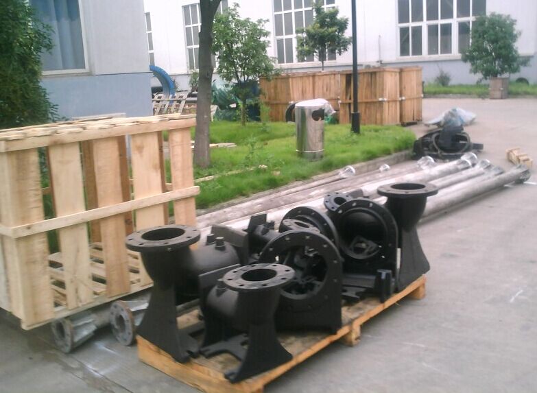
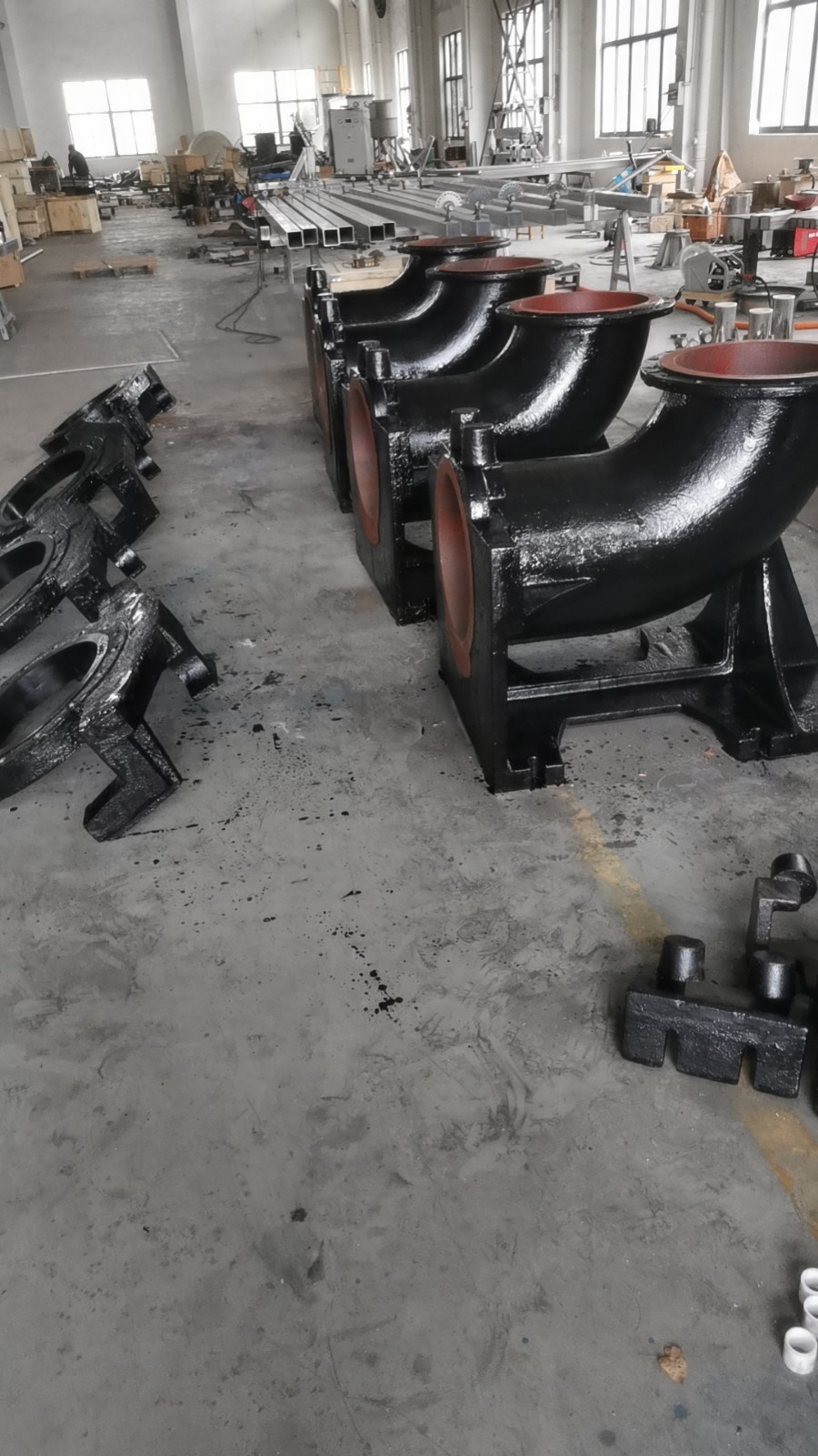
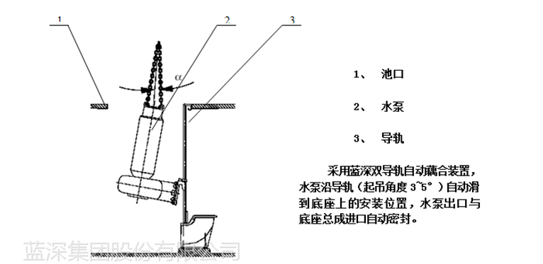
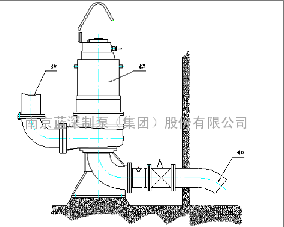
WQ submersible sludge pumps are generally equipped with automatic coupling.(Abbreviated as)The self-coupling installation system consists mainly of quick connectors, drainage bases, guide rails, and guide rail mounting brackets. During installation, the pump body and quick connector are tightly connected with bolts. The drainage base is first fixed to the pool with anchor bolts, and the quick connector guides the pump down the guide rail, automatically coupling with the drainage base through the self-coupling sealing surface. Once installed, the entire pump body and motor section are connected together via the pump's outlet and inlet flanges. The outlet of the submersible pump and the self-coupling base are sealed with a rubber gasket, and the pump is suspended in the air by the self-coupling system, utilizing its own weight to tightly compress the seal, ensuring reliable pipe sealing.
Submersible污水泵Installation Instructions for Dynamic Coupling Device
This description applies to the wet installation method of submersible pumps. (Please refer to the "Axial Diagram of Automatic Coupling Device" for the following part numbers.)
Pre-processing before installation. Note: Process A is required for DN200 to DN500. No process is needed for DN50 to DN150.
1. Location of the base (11) foot bolt holes.
According to the design construction drawings, before the concrete is poured into the wastewater pond, the foot bolt holes for the base (11) installation should be pre-drilled. The center of the pre-drilled holes aligns with the position of the base fixing bolts as indicated in the base fixing bolt layout diagram (see Table 1), with the size of the pre-drilled holes being 100*100 square holes.
2. Further approve that the Z-axis aligns with the center of the wall exit pipe, as well as the centerline of the foot bolt预留孔 and the centerline of the pool opening support block, all within the same axis plane. The dimensions must comply with the installation system diagram before pouring can commence.
B. Installation Process
Determine the position of the bearing block (2).
Draw a vertical line on the pool mouth wall adjacent to the drainage pipe, ensuring the line is within the plane of the center of the drainage pipe. This vertical line serves as the symmetrical reference line for installing the support block (2).
2. Install support block (2)
Please provide the Chinese content that needs to be translated into American English.2) The central line aligns with the installation baseline at the pool mouth. Drill two holes at the center of the pool wall according to the slot distance of the support block (2), referencing the size of the expansion bolt. Insert the expansion bolt (1) to secure the support block (2), but do not tighten it completely.
3 - a Foundation Mount (DN50~DN150)
3.1 - Ensure the correct placement of the base, place the base at the bottom of the pool. Hang a plumb line from the self-supporting block (2), aligning it with the centerline of the support block (2). Locate the centerline of the base (11) using the plumb line, and make sure the centers of the two cones on the support block (2) and the two cones on the base (11) are on the same level. Mark the position of the base (11)'s ground screw holes.
3.2 - Bottom Bracket (11): Remove the bottom bracket (11), drill holes at the marked positions using the correct size for the expansion bolt (12), clean out any debris from the holes, place the bottom bracket (11) back, insert the bolt (12), and tighten.
3 - Base Mount (DN200~DN500)
3.1b - Correct Installation Position of the Base (11): Place the base (11) at the bottom of the pool. Hang a plumb line from the self-supporting block (2) so that it aligns with the centerline of the block (2); locate the centerline of the base (11) using the plumb line, ensuring that the centers of the two cones on the self-supporting block (2) and the two cones on the base (11) are vertically aligned. Adjust the position of the anchor bolts in the pre-drilled holes.
3.2b - Pouring reserved holes, fill the reserved holes with concrete, ensuring the position of the foundation bolts within the holes and the length of the bolts extending above ground. Recheck the installation dimensions of the foundation bolts after the pouring is complete.
After casting, the maintenance period is15 days (Note: High-quality concrete and sufficient footer thickness are indispensable conditions for the vibration-free operation of the pump.)
4. Install导管
If the pool depth is less than6 meters, then saw the two tubes (10) to the appropriate length and securely install them between the support blocks (2) and the base (11). Ensure that each end is inserted into the conical shape of the support block (2) and base (11) respectively, and that the tubes remain vertically aligned.
If the depth of the pool is greater than6 meters, connect the conduit (10) to the short conduit (3) using the union (5), secure it with an internal hexagon bolt (4), and then place the conduit between the support block (2) and the base (11), ensuring it is perpendicular.
5. The system comprising the fixed support block (2), base (11), and conduit (10).
Re-inspect the bearing block2) Ensure that the导管 (10) is properly vertical with the base (11), aligning the centerline of the support block (2) with the centerline of the base (11) in the same plane. Then, securely tighten all screws in the fastening system, ensuring that there is no movement in either the vertical or horizontal direction for the entire system.
6. Drainage pipeline installation
According to the installation diagram, sequentially connect the drain pipes with bolts and sealing washers, and then attach the flexible rubber joints, elbows, wall outlets, swing check valves, and wedge gate valves. Fill the wall outlets with concrete to secure them to the wall.
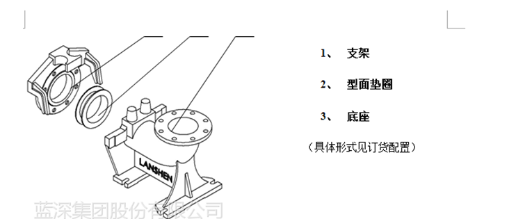
7. Assembly of brackets
Type Face Washers6) Within the embedded bracket (7), pay attention to the directional installation of the face washer (6). The rubber flange edge that is the same thickness as the electric pump flange surface is the one that interfaces with it, while the rubber flange with a thick and thin edge interfaces with the base. Ensure the thicker part is at the top of the installation hole, and secure the bracket to the pump outlet flange using bolt (9) and washer (8). To ensure sealing, tighten the bolts alternately diagonally.
8. Hoisting pump into place
Attach the chain to the lifting ring of the electric pump, hoist the pump, sliding it along the conduit into the sewage pond, and then secure it in place on the base.11) The ribbed plates on both sides, due to the weight of the pump itself, allow the pump to automatically achieve the correct working position, ensuring the sealing performance of the pump outlet with the base.
9. Adjust the float ball switch position
Users can adjust the float switch position according to design requirements or personal needs to control the start and stop of the electric pump based on the pool water level changes. The water level should submerge the impeller casing.
10. Attach recommendations
After installation, the concrete slope at the bottom surface can be irrigated. The choice of the slope around the wastewater pond should be suitable for the pond's dimensions. Generally, the horizontal to vertical dimension ratio is determined.2:1
11. Hoisting a pump
To facilitate the use of the pump for hoisting, the pump is equipped with a loop. Before lifting the electric pump, hang the loop from the crane hook, thread a nylon rope and chain through the round hole, straighten the rope end, and let the loop slide down the nylon rope and chain links. When positioned correctly, release the tension on the nylon rope, causing a link in the chain to engage and lock with the loop. At this point, you can hoist and elevate the pump. The loop can also be used to safely and conveniently place the pump in the intended location.
Self-coupled specifications and models of sewage pumps:
GAK50 Submersible Sewage Pump Automatic Coupling Device (Cast Iron)
GAK65 Submersible Sewage Pump's Automatic Coupling Device (Cast Iron)
GAK80 model submersible sewage pump with automatic coupling device (cast iron)
GAK100 Submersible Sewage Pump's Automatic Coupling Device (Cast Iron)
GAK150 Automatic Coupling Device (Cast Iron) for Submersible Sewage Pumps
GAK200 Automatic Coupling Device (Cast Iron) for Submersible Sewage Pumps
GAK250 Automatic Coupling Device (Cast Iron) for Submersible Sewage Pumps
GAK300 model submersible sewage pump with automatic coupling device (cast iron)
GAK350 Submersible Sewage Pump with Automatic Coupling Device (Cast Iron)
GAK400 Submersible Sewage Pump's Automatic Coupling Device (Cast Iron)
GAK450 Submersible Sewage Pump's Automatic Coupling Device (Cast Iron)
GAK500 Submersible Sewage Pump with Automatic Coupling Device (Cast Iron)
GAK600 Submersible Sewage Pump's Automatic Coupling Device (Cast Iron)