


I. Overview
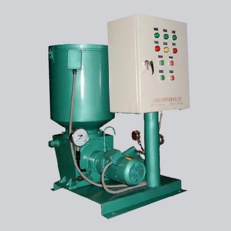
The ASE-PB series electric lubrication pumps are suitable for centralized lubrication systems with high lubrication frequency, long piping lengths, and dense lubrication points in single or double-line dry and semi-dry oil systems. They serve as the conveying device for delivering lubricants. They can also be equipped with mobile trolleys, hoses, oil guns, and cables to form a portable electric lubrication pump unit, which is suitable for individual machines with low lubrication frequency, fewer lubrication points, large oil supply, and where centralized lubrication is not feasible, for mobile oil supply and lubrication.
This series of lubrication pumps is an electric high-pressure plunger type. The working pressure can be adjusted at will within a range of 40MPa, featuring dual overload protection. The oil storage tank is equipped with an automatic oil level alarm device. With an electrical control box, it can achieve automatic full control of a dual-line centralized lubrication system and monitor the system.
Section II: Working Principle
The decelerating motor is mounted on the connecting flange of the pump element, driving the slider to perform a straight reciprocating motion through the eccentric shaft, and rotating the spiral oil-pressing plate and scraper plate clockwise (this mechanism is not required when using lubricating oil), uniformly pressing the softened grease through agitation around the pump element's oil intake.
The pump contains two sets of pistons, each consisting of 1 working piston and 2 control pistons. When the working piston in one set completes the suction process, the working piston in the other set pushes grease towards the outlet. As shown in the diagram, when the slider moves to the left, the upper set of pistons finish suction and begin a new working cycle. At this point, the lower set pistons 1 and 2 move to the left; piston 2 reaches the oil under the force of the spring, and the lower set pistons complete the pressure oil process, closing the outlet at the limit position. Meanwhile, piston 1 continues to move to the left, forming a vacuum between pistons 2 and 1, which increases continuously as piston 1 moves left. The slider moves to the limit position, and piston 1 opens the suction port, allowing grease to be drawn in. If the spring force is insufficient to push piston 2 to the limit position, the rod 3 will be forced by the slider to push piston 2 to the limit position. At the same time, the upper set pistons 1, 2, and 3 move to the left; piston 1 closes the suction port first, and the grease drawn in is pushed to the left by piston 1. When piston 2 opens the outlet, the movement of piston 2 and rod 3 stops. Piston 1 continues to move left, pushing grease out from the outlet. Piston 1 and 2 have also reached the limit position, completing half a cycle. This cycle repeats, with the two sets of pistons alternately pushing grease out from the outlet. The grease pushed out is then filtered through a filter on the pump's connecting flange before being supplied to the system.
ThreeUser Instructions
1. This series of electric lubrication pumps should be installed indoors in areas with minimal dust for ease of greasing, adjusting, inspecting, repairing, and cleaning. They should ideally be placed at the center of the system to minimize pipeline length, maintain low pressure drop, and ensure the pump generates enough pressure to overcome the back pressure at the lubrication points. If installed outdoors or in harsh environments, protective measures must be taken.
2. The set pressure of the pressure regulating valve for the pump can be adjusted arbitrarily within the range of 0~40MPa. It is not allowed to exceed the nominal pressure of the pump (40MPa) during operation.
3. In the event of a system malfunction causing the pressure to reach approximately 50MPa, the safety plate will rupture. Investigate the cause and rectify it before installing a new safety plate.
4. Refilling the lubricant into the reservoir must be done using the ASJB-3.3 electric fuel pump, inserting it through the reservoir's replenishment port.
5. The thin-film capacity indicator in the oil storage tank is only suitable for grease. When using a lubricating oil medium, it must be replaced with a float-type capacity indicator.
6. After the initial two months of use, the electric reducer must be topped up with an appropriate amount of 3# molybdenum disulfide grease through the exhaust port, and this should be repeated every four months thereafter.
7. This series of electric grease pumps is designed for indoor installation.
