


I. Overview
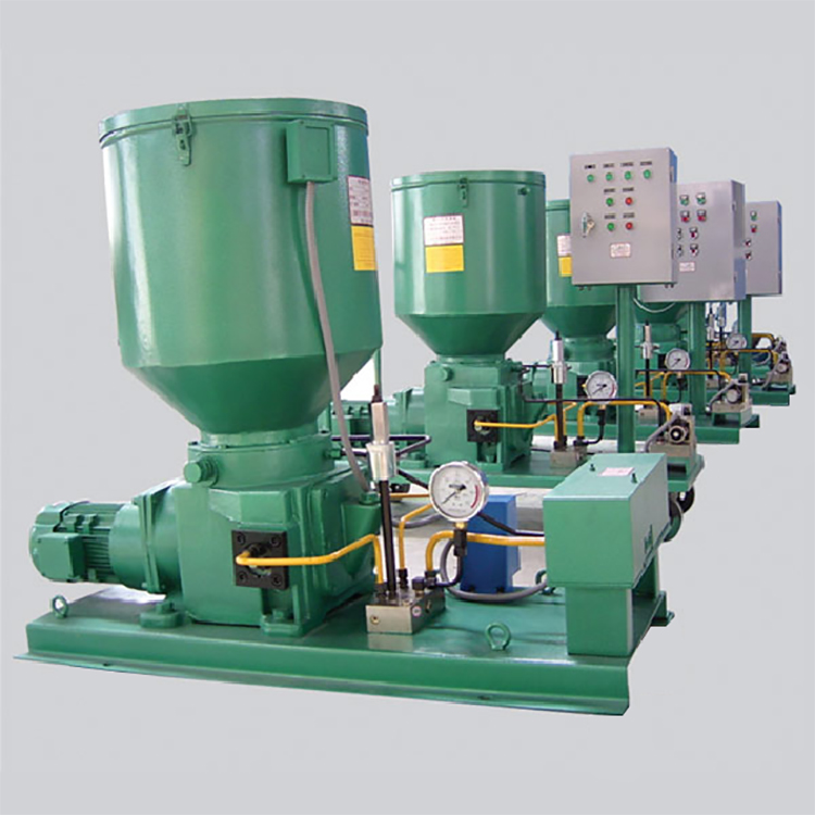
2RHS electric lubrication pump, suitable for dual-line centralized lubrication systems with numerous lubrication points, wide distribution, and high oiling frequency, delivering grease to lubrication locations through distributors. Particularly suitable for large-scale equipment and production lines.
The pump features a dual-pump, dual-valve design, with one in operation and the other as a spare. In case of maintenance on one of the pumps, the system can remain operational by switching the valves. Additionally, an oiling valve block is equipped, allowing for lubrication to be added to the oil reservoir of any pump by switching the valves. Moreover, the pump outlet is fitted with a filter to ensure the supply of clean oil to the main pipeline.
Part Two: Working Principle
The reducer drives the scraper and spiral oil press plates in a clockwise rotation via an eccentric shaft. The lubricating grease scraped off the drum wall is mixed and then delivered to the pump components by the spiral oil press plates.
There are two groups of pistons inside the pump, each consisting of one working piston and one control piston. When the working piston in one group completes the suction process, the working piston in the other group pushes grease towards the outlet. As shown in the figure, as the crankshaft (1) rotates and drives the inner and outer slides (2, 4) to move left, the control piston (3) opens the suction channel, and the main piston (5) completes the pressure process. After pressure is finished, the main piston (5) continues to move left,吸入 lubricant to its limit position, and the corresponding control piston (3) closes the suction channel and opens the pressure channel. When the inner and outer slides (2, 4) move right, the main piston (5) begins to pressure oil, which flows through the outlet channel to the one-way valve at the pump cylinder outlet and is expelled outward. Upon reaching its limit position, the main piston (5) finishes the pressure process, and the control piston (3) also closes the outlet channel and opens the suction channel to prepare for the next work cycle.
Section 3: Installation, Commissioning, and Operation
1. Prior to use, it is mandatory to fill the reducer with 50# mechanical oil to the level indicated by the oil gauge.
2. The set pressure for the pump's overflow can be adjusted arbitrarily within the range of 0-40MPa. It is not allowed to exceed the nominal pressure of the pump (20MPa or 40MPa) during use. Clean grease must be used. Contaminated grease often causes malfunctions in the pump and system, so a grease pump must be used when refilling to first add some lubricating oil, as it flows well and fills all parts, aiding in air exclusion. If certain lubrication areas cannot use lubricating oil, the pump must operate until it is air-free and grease is discharged from the end of the pipeline.
Section 4: Maintenance and Care
1. This pump is suitable for indoor use; protective measures must be taken when used outdoors or in harsh environments.
2. When the pressure in the system reaches approximately 23MPa or 40MPa due to certain failure causes, the safety plate installed in the oil collection block will burst, and the grease will overflow from the overflow pipe. Before installing a new safety plate, it is essential to identify the cause of the system overpressure and rectify the fault. When replacing the new safety plate, the convex side must be facing outward.
