
Product Details
Transmission shaft series test machines, reinforced扭杆pre-torsion machines


产品Price 4.80/Tai
最小起订Quantity:1 Tai 供货总Quantity: 10000 Tai


I. Application The Constant Velocity Joint Multi-Function Performance Test Bench is a testing equipment used for evaluating various performance indicators of Constant Velocity Joints. Driven by a servo motor and controlled by a computer system, the bench automatically collects and processes data, records test parameters, plots measurement curves, and can print test reports and curves. It is an ideal device for conducting performance tests on Constant Velocity Joints. II. Test Bench Structure Composition The test bench is mainly composed of the main system (divided into two main frames for improved measurement accuracy, gap measurement, and other performance tests), the computer measurement and control system, and the data processing system. (1) Performance Console Host System: The main system consists of the mainframe, workbench, portable test devices, and fixed test devices. 1. The mainframe is made by welding sections, which serve to support the workbench and ensure rigidity during testing. The work platform on the frame serves as the installation base for other devices. 2. The mobile testing device is arranged on the left side of the host worktable. It consists of three parts: the small sliding platform measuring device, the large sliding platform measuring device, and the oscillating device. The sliding platform's moving measuring device consists of a rotating unit and an extendable moving unit. The rotating unit includes a servo motor, main shaft box, torque sensor, and chuck, designed to generate rotational motion, test twist angles, and torque. The extendable unit is composed of linear guides, ball screw, stepper motor, load sensor, and displacement sensor, which are used to drag the main shaft box for axial displacement. The large sliding platform mobile testing device is composed of linear guides, ball screw, and moving motors, used as an auxiliary moving device for measuring sliding curves and also for adjusting the test space. The oscillating device consists of an oscillating platform, main shaft, torque sensor, reducer, and servo motor, designed to generate the oscillating angle of the sliding end and test the oscillating torque. 3. The fixed-end testing device is positioned at the right end of the workbench, consisting of three units: a universal joint mounting device, a swinging device, and a horizontal axial movement device. The universal joint installation device consists of a rotating mechanism, tailstock, chuck, etc. The rotating mechanism ensures the universal joint can rotate freely when testing dynamic performance. The oscillating device structure is the same as the sliding end oscillating device. The horizontal axial movement device consists of a stepper motor, ball screw, linear guide rail, and moving platform. The purpose of the horizontal axial movement device is to adjust the center position of the universal joint based on different center-to-face distances (distance from the center of the universal joint to the end face) in order to align the center of the universal joint with the oscillation center of the test bench. (II) Gap Stand Mainframe System: The main system consists primarily of the main frame, workbench, rotating drive measuring device, linear drive measuring device, and clamping devices. 1. The mainframe is constructed using welded connections for molding, serving to support the workbench and ensure rigidity during testing. The work platform on the frame serves as the installation foundation for other devices. 2. The rotating drive measuring device consists of a servo motor, reducer, torque sensor, chuck, etc., used to drive assemblies or ball joints to produce rotational motion and measure the circumferential clearance. 3. The linear drive measuring device consists of an electric cylinder, force sensor, displacement sensor, and chuck, which drives the fixed-end ball joint to produce linear motion and measure the axial clearance. 4. The holding device is used to grip the intermediate shaft of the drive shaft during the measurement of the axial clearance at the fixed end.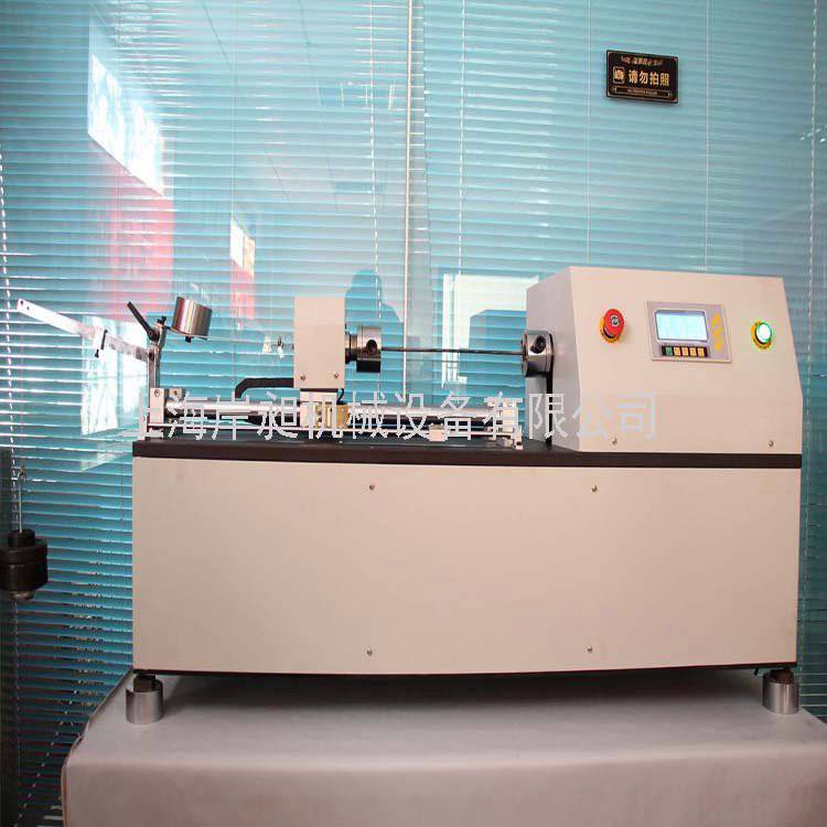

Phone Consultation