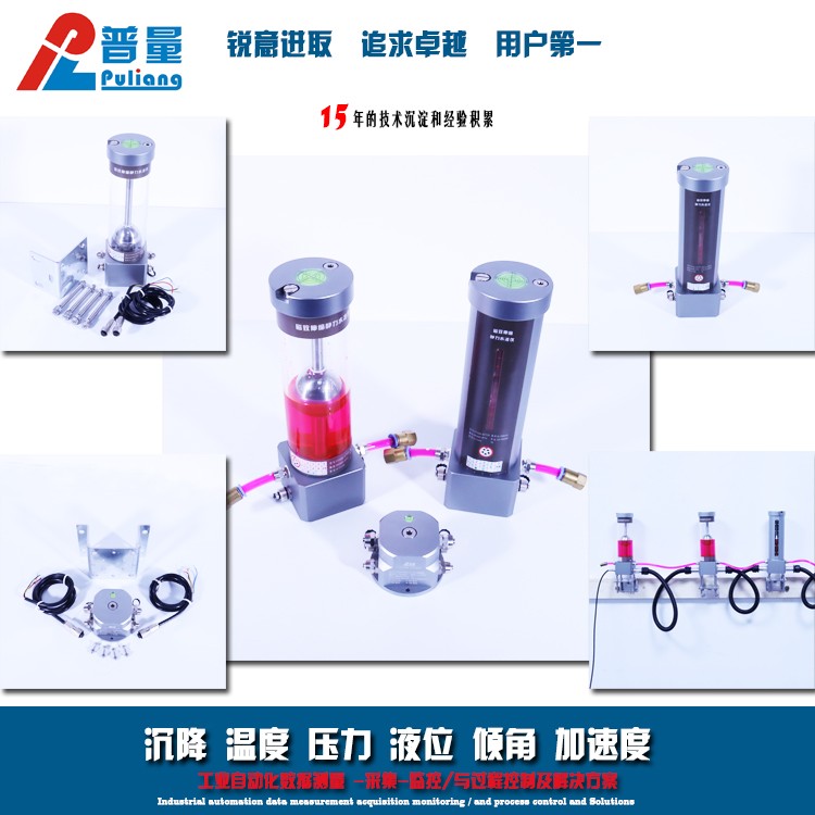

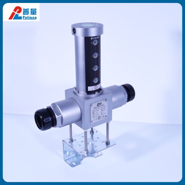

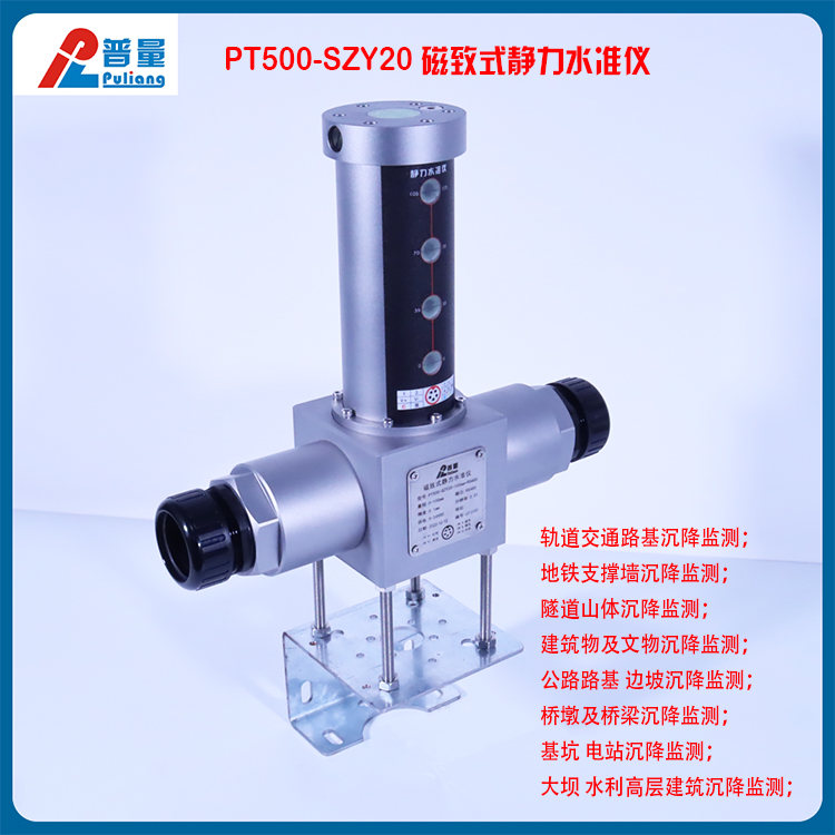
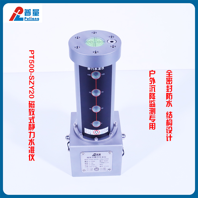
Magnetic Resonance Hydrostatic Level Gauge, High Precision, Excavation Pit, Tunnel, Railway, Highway, Settlement Monitoring, Outdoor Installation, PT500-SZY20
Product Overview:
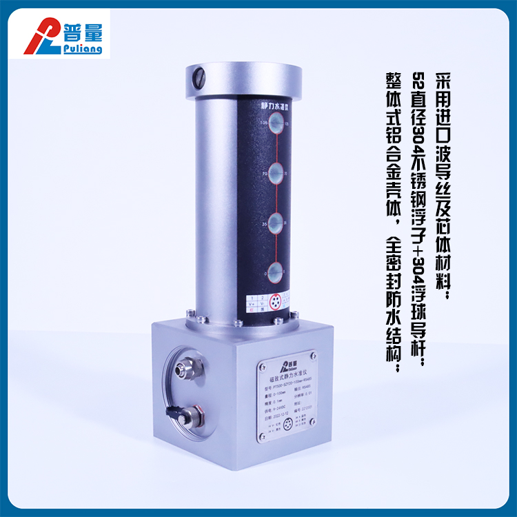
Utilizing imported waveguide fiber and core materials.
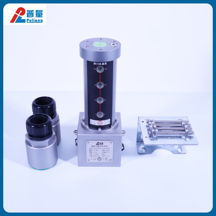
52mm diameter 304 stainless steel float + 304 ball float rod
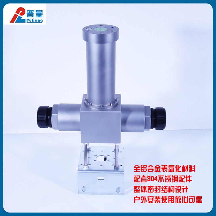
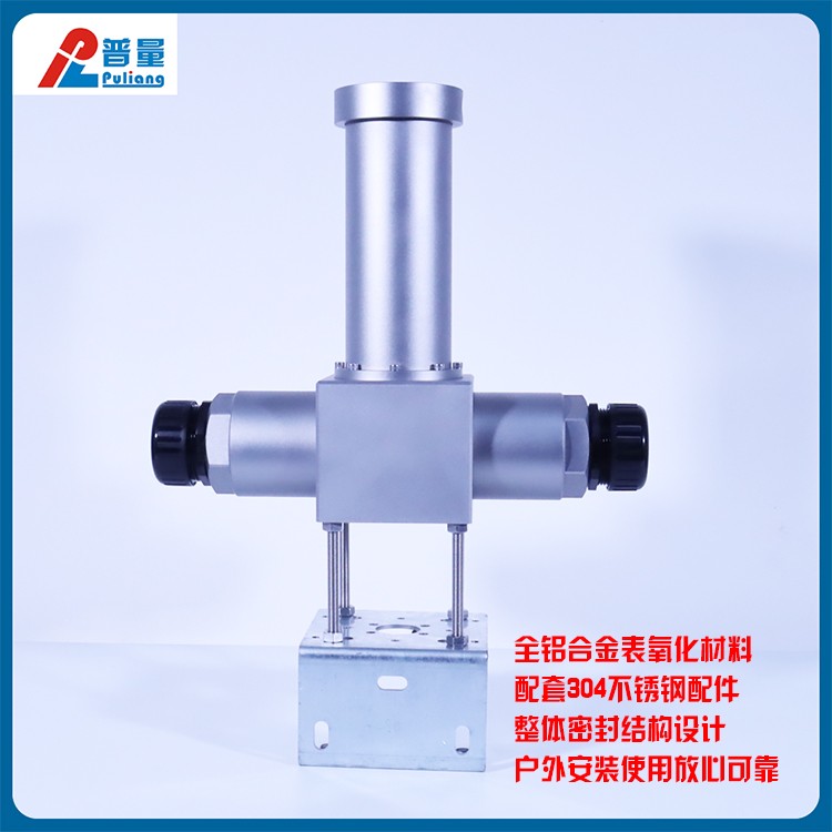
Integrated aluminum alloy housing, fully sealed and waterproof structure.
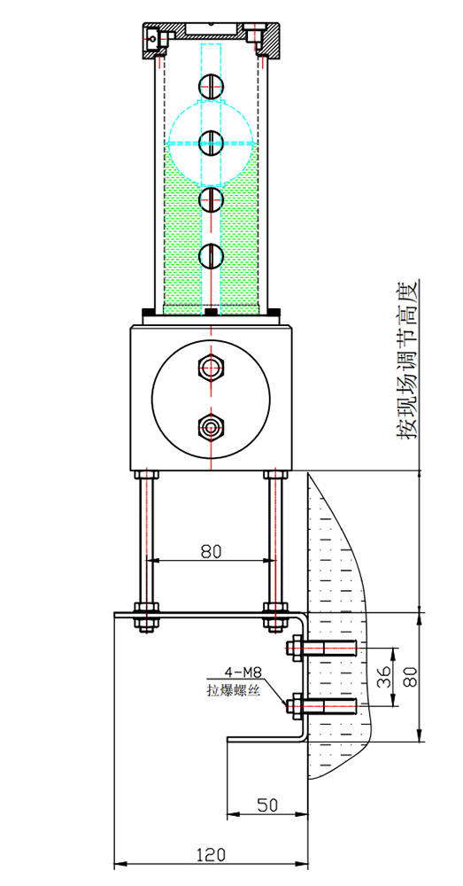
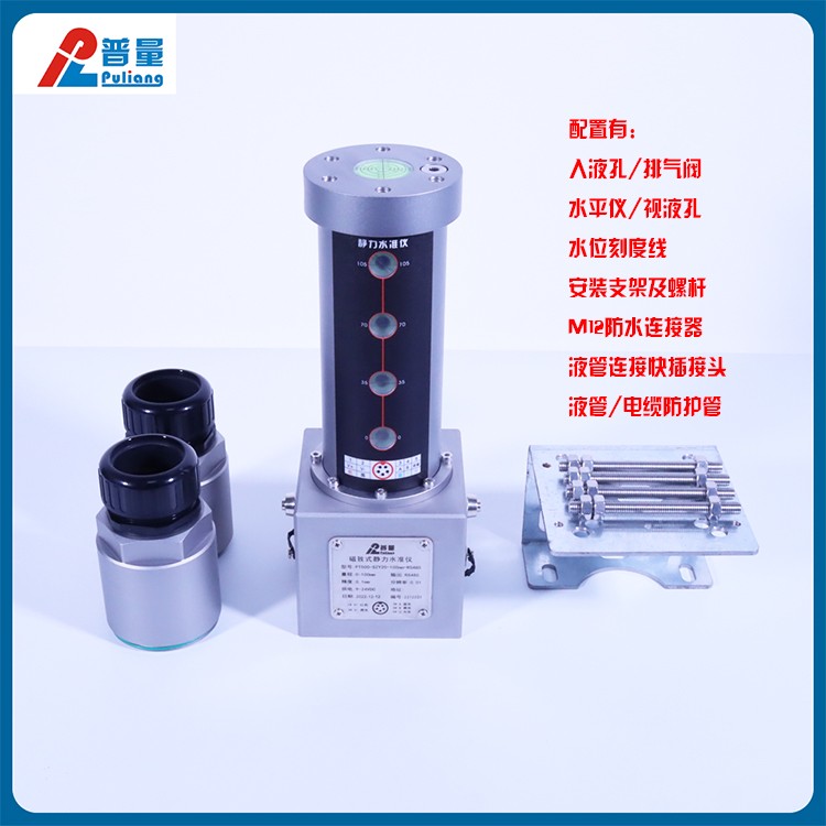
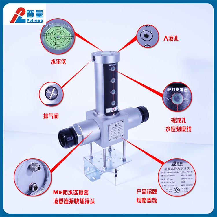
Matching liquid inlet holes, exhaust valves, level gauges, mounting brackets.
10mm tube connection quick plug; M12 waterproof connector.
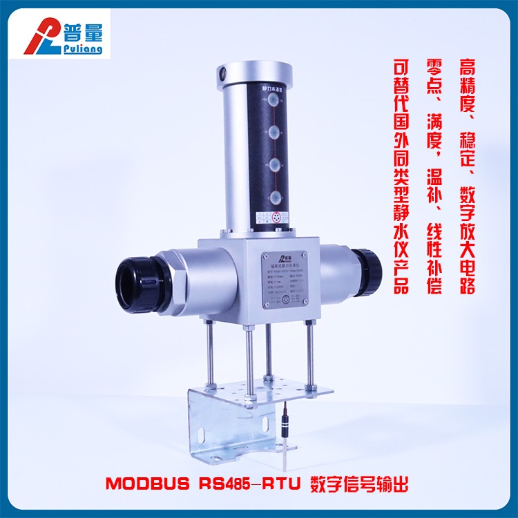
High precision, stable, digital amplification circuit; Zero point, full scale, temperature compensation, linear compensation.
MODBUS RS485-RTU Digital Signal Output
Alternative to foreign similar hydrostatic level instruments.
Custom outdoor waterproof connection pipes; anti-freeze fluid and liquid tubes, as well as RS485 communication cables.
Supply PT500-990 wireless 4G data collection module and third-party monitoring platform as required.
As required, provide locally compatible supervisory software.
The PT500-SZY20 Magnetic Inductive Hydrostatic Level Gauge is primarily used for:
Railway track subgrade, subway support wall settlement monitoring
Tunneling and building settlement monitoring above the hillside.
Highway subgrade, slope, and pier settlement monitoring
Excavation, nuclear power plant, and hydroelectric power plant settlement monitoring.
Dam and hydraulic枢纽的基础沉降 monitoring for high-rise buildings
Bridge, foundation, and tunnel safety management;
Grip parameters such as the environment, traffic, structural stress, and deformation of the monitored object.
Real-time assessment of bridge operational status and prediction of functional changes in the bridge.
Assess signs and trends of structural performance degradation to enable maintenance units to take timely maintenance measures.
Measure the settlement of the support base, measure the expansion joint changes
Measure anchor plug displacement

Model Naming:
PT500-SZY20-100mm-RS485
PT500: General Quantity Category
SZY20: Model Specification
100mm: Travel Range
RS485: Output Signal
PT500-SZY20 Magnetic-Inductive Linear Variable Differential Transformer (LVDT) Hydrostatic Level Gauge Main Technical Parameters:
Range: 0-100mm; 200mm; 300mm;
±0.1mm;
Non-linear: ≤0.05%FS
Repeatability: ≤0.002%FS (1μm)
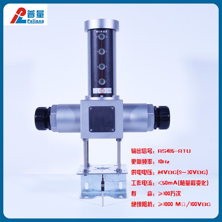
Output Signal: RS485-RTU
Update Frequency: 10 Hz
Supply Voltage: 24VDC (9-30VDC)
Working Current: <50mA (varies with range)
Life span: ≥1 million cycles
Insulation Resistance: ≥1000 MΩ/100VDC
Ambient Temperature: -40~70℃
Humidity/Dew Point: 90% humidity, no condensation
Temperature Coefficient: <30ppm/°C
Electrical Connections: M12 Waterproof Electrical Connectors
Process Connection: 10mm Liquid Tube Quick Connector
Protection Class: IP67
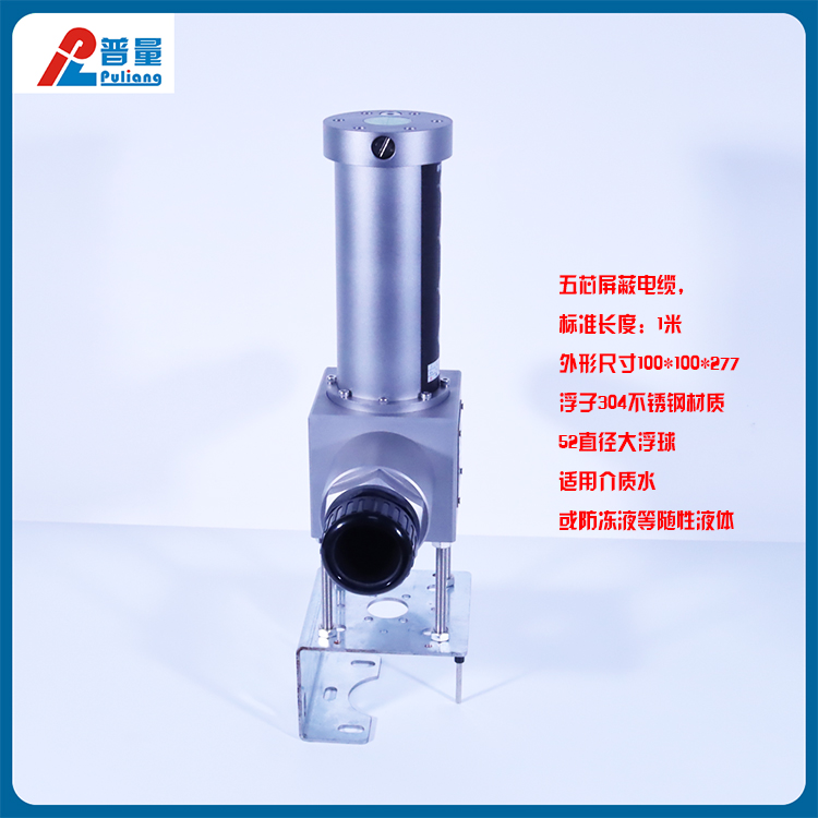
Connectivity Cable: 5-core shielded cable, Standard Length: 1 meter
Dimensions: 100*100*277
Buoy Specifications: 304 stainless steel, 52mm diameter large buoy ball
Applicable Medium: Water or antifreeze and other liquid substances (ensure the liquid does not freeze based on the environmental temperature of the application installation area)

.jpg)

Measurement Principle and Installation:
The hydrostatic level system, also known as a connecting tube level instrument, consists of at least two observation points, with each point equipped with a hydrostatic level instrument. The storage containers of the hydrostatic level instruments are completely connected by a fluid conduit. Inert liquid is injected into the storage containers. Once the liquid surface is completely still, the liquid surfaces in all connected containers within the system should be at the same geoid level. At this point, the liquid level in each container is measured by the sensor, with the initial liquid level values being: H10, H20, H30, H40.
As shown:
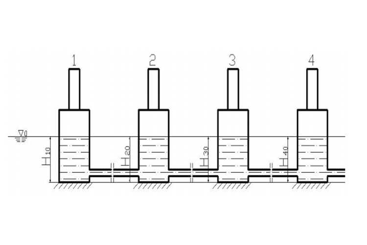
Settlement Calculation:
Assuming the measurement point 1 as the reference point, with point 2 experiencing ground settlement, point 3 experiencing ground uplift, point 4 with no change, etc., after the liquid level in the system reaches a balanced state, a new datum level Vi0 is formed. The new liquid level values in the connecting containers at each measurement point will be: H1, H2, H3, H4, and the respective liquid level change amounts will be calculated as:
△h1=H1-H10 △h2=H2-H20
△h3=H3-H30 △h4=H4-H40
When point 1 is selected as the reference point, the vertical displacement (subsidence) of other measuring points relative to the reference point is:
△H2=△h1-△h2 △H3=△h1-△h3 △H4=△h1-△h4
As shown: